

Gate line driver circuits for LCD displays
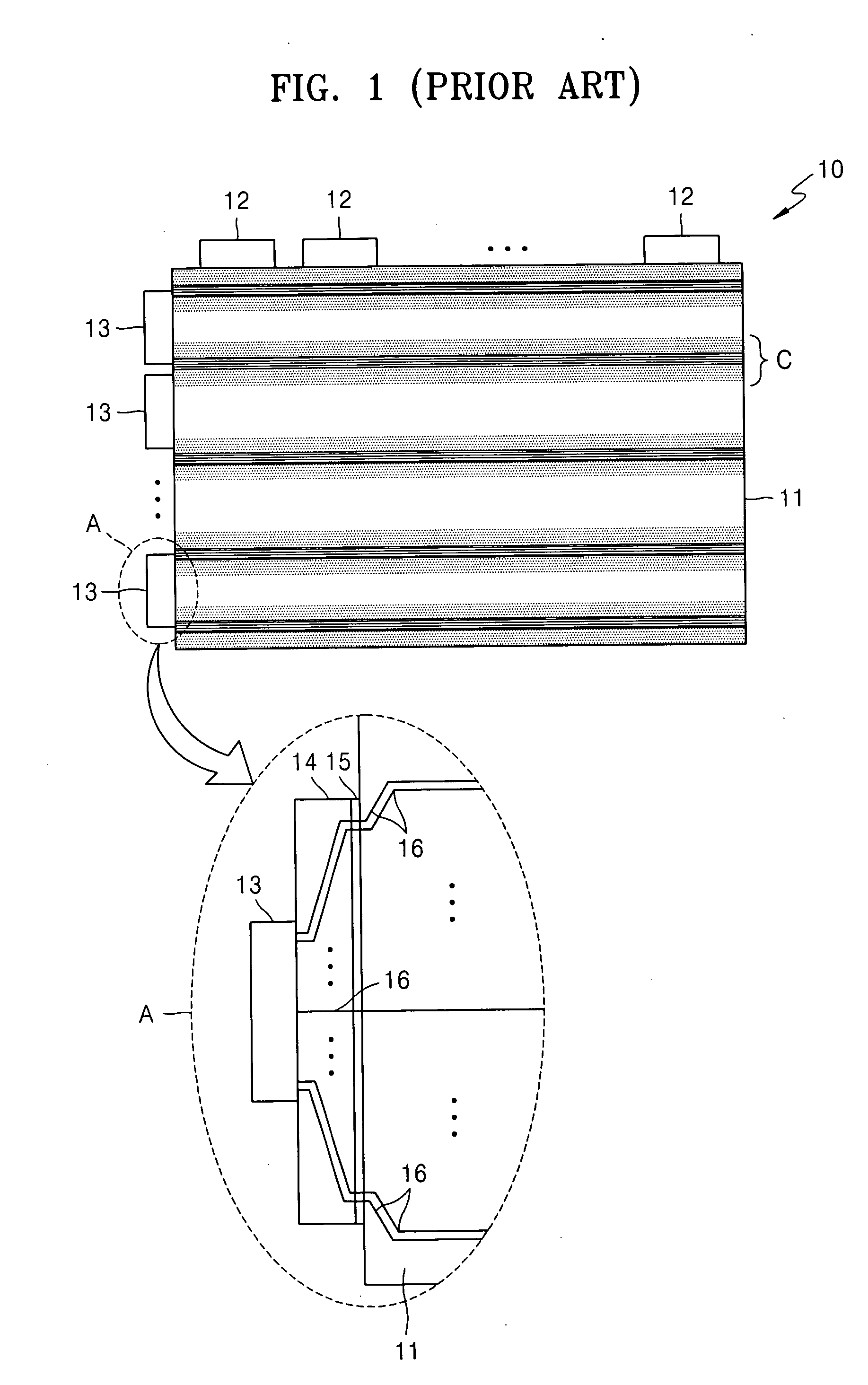
a technology of gate line driver and lcd display, which is applied in the direction of static indicating devices, non-linear optics, instruments, etc., can solve the problem that the quality of an image displayed on the lcd panel b>11/b> may be relatively poor, and achieves a high degree of timing overlap
- Summary
- Abstract
- Description
- Claims
- Application Information
AI Technical Summary
Benefits of technology
Problems solved by technology
Method used
Image

Examples
Embodiment Construction
[0017] The present invention now will be described more fully herein with reference to the accompanying drawings, in which preferred embodiments of the invention are shown. This invention may, however, be embodied in many different forms and should not be construed as being limited to the embodiments set forth herein; rather, these embodiments are provided so that this disclosure will be thorough and complete, and will fully convey the scope of the invention to those skilled in the art. Like reference numerals refer to like elements throughout and signal lines and signals thereon may be referred to by the same reference characters. Signals may also be synchronized and / or undergo minor boolean operations (e.g., inversion) without being considered different signals. The suffix B (or prefix symbol “ / ”) to a signal name may also denote a complementary data or information signal or an active low control signal, for example.
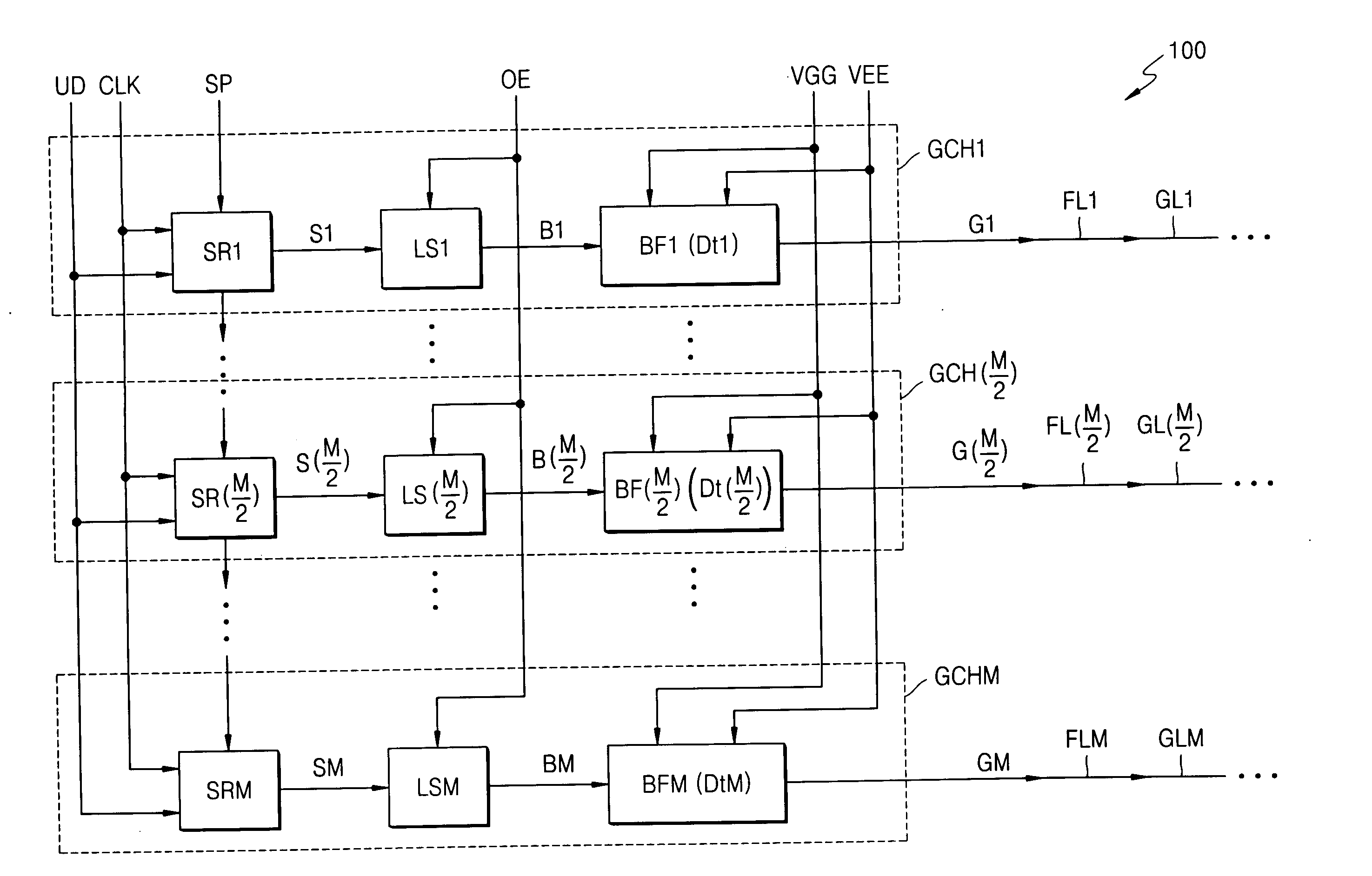
[0018]FIG. 4 is a block diagram of a gate driver integrated circ...
PUM
 Abstract
Description
Claims
Application Information