Image display unit

a technology of image display and unit, applied in the field of image display, can solve the problem of not being able to reduce the moire sufficiently

Inactive Publication Date: 2006-06-01
SANYO ELECTRIC CO LTD
View PDF0 Cites 18 Cited by
  • Summary
  • Abstract
  • Description
  • Claims
  • Application Information

AI Technical Summary

Benefits of technology

[0019] In the above-described oblique barrier configuration, it may be possible that the number of viewpoints is set to be two, the separating mean is formed of a liquid crystal panel and capable of switching between a separation and a non-separation, and as a result of corners of the aperture portion that is the separatin...

Problems solved by technology

In addition, in the apertures 12a shown in FIG. 14, a manner of a diffraction changes in the ...

Method used


Image

  • Image display unit
  • Image display unit
  • Image display unit

Examples


Embodiment Construction

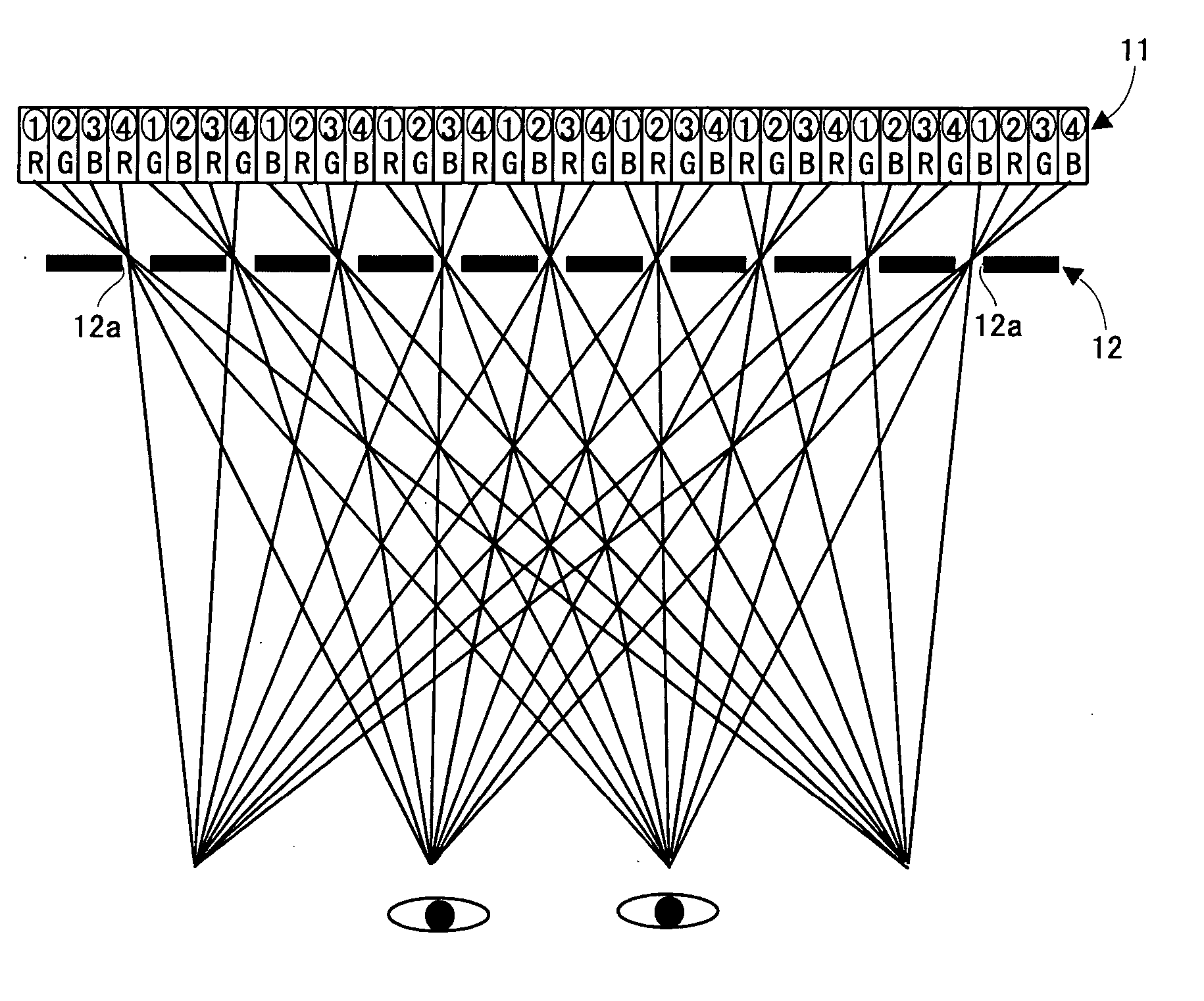
[0034] Below, an image display of an embodiment of the present invention will be described based on FIG. 1 to FIG. 9. It is noted that regarding an entire configuration of the image display, the configurations in FIG. 10 and FIG. 11 described in the prior art section are adoptable, and in order to avoid a redundancy due to duplicated descriptions, a description of the entire configuration is omitted.

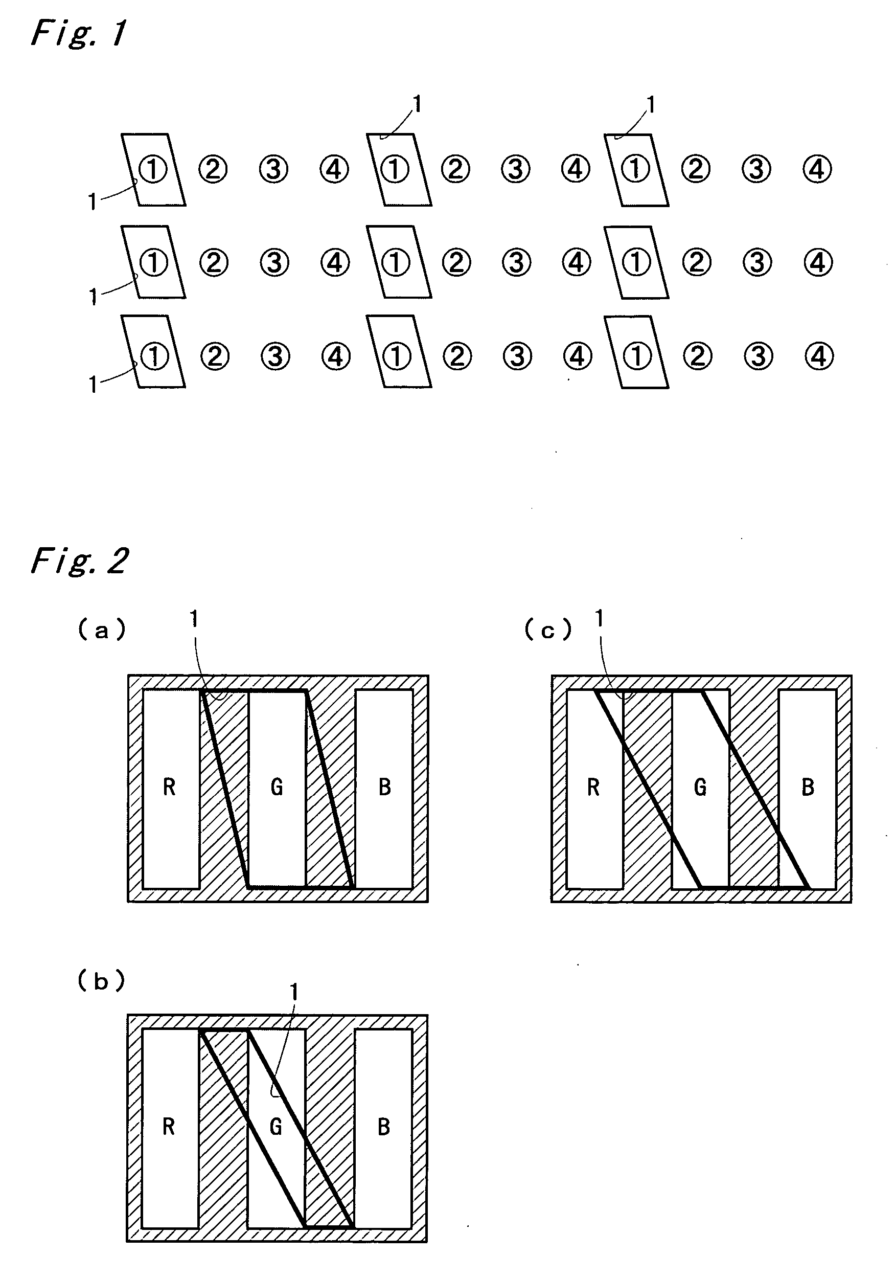
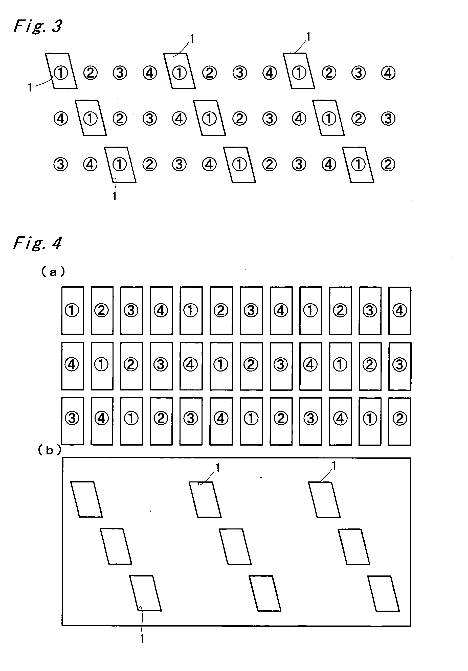
[0035] In a configuration shown in FIG. 1, four images (dots) of “image {circle around (1)}, image {circle around (2)}, image {circle around (3)}, and image {circle around (4)}”, i.e., a minimum unit image group, are repeatedly aligned in a horizontal direction of a screen 1, and the minimum unit image groups exist in such a manner as not to be deviated on each line. One aperture 1 exists corresponding to each minimum unit image group, and in a contour of each aperture 1, as shown in FIG. 2, oblique line portions that are non-parallel to a contour of each of the dots (R, G, B). Each ape...


PUM


Abstract

An image display that separates by a separating means respectively different images displayed on a screen so as to be introduced to an observer, and is constituted as a stereoscopic image display, and others. In a case of a four-viewpoint stereoscopic image display, an image {circle around (1)}, an image {circle around (2)}, an image {circle around (3)}, and an image {circle around (4)} having a binocular parallax in a horizontal direction of the screen are aligned at a predetermined pitch, and a minimum unit image group of this “image {circle around (1)}, image {circle around (2)}, image {circle around (3)}, and image {circle around (4)}” repeatedly exists. One aperture (1) is formed corresponding to the minimum unit image group, and in a contour of each aperture (1), oblique line portions that are non-parallel to the contour of a dot exist.

Description

TECHNICAL FIELD [0001] The present invention relates to an image display used for allowing an observer to perform a stereoscopic vision, and allowing a plurality of observers to see different images. PRIOR ART [0002] From the past, as a method for realizing a stereoscopic vision display without requiring special glasses, a parallax barrier method, a lenticular lens method, and others are known. These methods are methods in which a right-eye image and a left-eye image having a binocular parallax are displayed on a screen one after the other in a vertical stripe shape, for example, and this displayed image is separated by a parallax barrier, a lenticular lens, and others, and introduced to each of right and left eyes of an observer so as to allow a stereoscopic vision to be performed. [0003]FIG. 10 is a descriptive diagram illustrating a principle of a stereoscopic image display of a four-viewpoint stereoscopic vision method. An image {circle around (1)}, an image {circle around (2)},...

Claims


Application Information

Patent Timeline
IPC IPC(8): G02B27/22G02F1/13G02F1/1343G03B35/24H04N13/00
CPCH04N13/0409H04N13/0422H04N13/324H04N13/31G09F9/00G09F19/14
Inventor MASHITANI, KENHAMAGISHI, GORO
Owner SANYO ELECTRIC CO LTD
Why Eureka
Try Eureka