Optical film for backlight unit and method for manufacturing the same

a technology of optical film and backlight unit, which is applied in the field of optical film for backlight unit, can solve the problems of reducing light brightness, reducing productivity, and adsorption of foreign substances in films, so as to prevent the adsorption of foreign substances and the generation of scratches, reducing light loss, and improving productivity

Inactive Publication Date: 2006-06-01
LMS +1
View PDF2 Cites 22 Cited by
  • Summary
  • Abstract
  • Description
  • Claims
  • Application Information

AI Technical Summary

Benefits of technology

[0008] The present invention is conceived to solve the aforementioned problems. An object of the present invention is to provide an optical film for a backlight unit capable of reducing a loss of light, preventing the adsorption of foreign substances and the scratch generation during its assembly process, achieving productivity improvement and manufacturing cost reduction, and adjusting the brightness thereof, and a method for manufacturing the optical film for the backlight unit.

Problems solved by technology

However, in such a related art backlight unit, there is a problem in that a brightness of light is reduced due to a loss of a portion of light between the diffusion film and the pair of prism films because the films are used to diffuse and collect the light transmitted from the light guide plate.
Further, there is another problem in that the adsorption of foreign substance in and scratches due to the contact of foreign substances with the films are highly likely to occur during the subsequent assembly process of the respective diffusion and prism films.
Furthermore, there is still another problem in that the decrease of productivity due to the increase of assembly process and the increase of manufacturing Cost due to the increase of the number of films can be brought about, because the processes of assembling the diffusion and prism films are separately carried out when assembling the backlight unit.
Therefore, there is a still further problem in that it causes the addition of a process of stacking the prism films one above another, the productivity decrease and manufacturing cost increase, and it is substantially difficult to ensure a desired brightness due to inherent difficulty in the adjustment of brightness.

Method used


Image

  • Optical film for backlight unit and method for manufacturing the same
  • Optical film for backlight unit and method for manufacturing the same
  • Optical film for backlight unit and method for manufacturing the same

Examples


Embodiment Construction

[0024] Hereinafter, the present invention will be explained in detail with reference to the accompanying drawings.

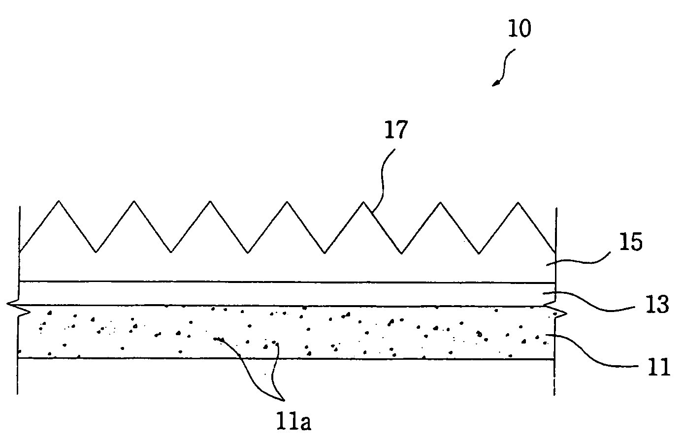
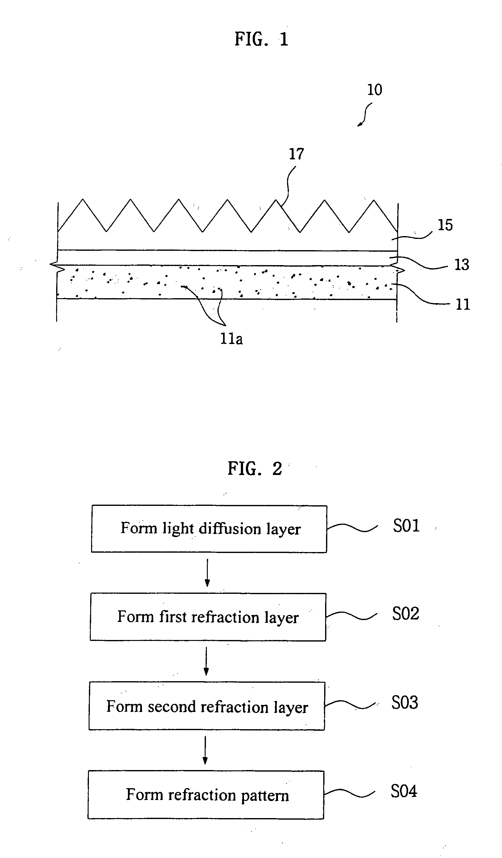
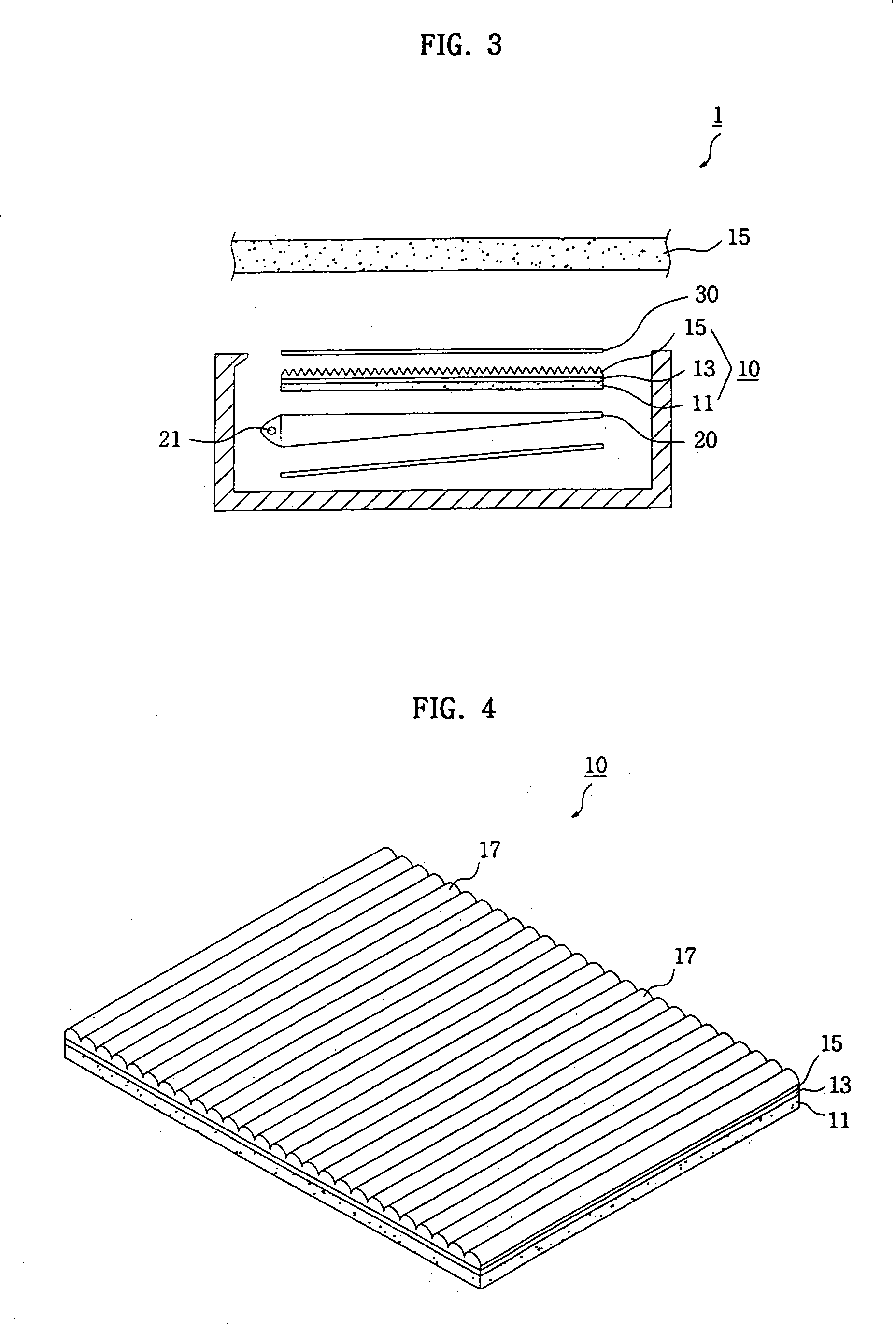
[0025]FIG. 1 is a sectional view of an optical film for a backlight unit according to the present invention. Referring to the figure, the optical film 10 for a backlight unit of the present invention comprises a light diffusion layer 11 for diffusing light, a first refraction layer 13 for refracting the light diffused in the light diffusion layer 11 in a direction perpendicular to a surface of the film with a predetermined index of refraction, and a second refraction layer 15 which has a relatively high index of refraction compared to the first refraction layer 13 and collects and refracts the light passed through the first refraction layer 13 in the direction perpendicular to the surface of the film.

[0026] The light diffusion layer 11 is manufactured in the form of a soft sheet made of a transparent polyester-based resin, and light diffusing particles 11a for diffusin...


PUM

PropertyMeasurementUnit
index of refractionaaaaaaaaaa
transparentaaaaaaaaaa
refractionaaaaaaaaaa

Abstract

The present invention relates to an optical film for a backlight unit and a method for manufacturing the same. The optical film of the present invention comprises a light diffusion layer in which light diffusing particles are distributed, a first refraction layer which has a relatively low index of refraction and is formed integrally on a top surface of the light diffusion layer, and a second refraction layer which has an index of refraction relatively higher than that of the first refraction layer and is formed integrally on a top surface of the first refraction layer and formed with a refraction pattern on a surface thereof. According to the present invention, the loss of light can be prevented, the adsorption of foreign substances in and the resultant scratch generation on the films can be avoided during the assembly process of the backlight unit, the productivity improvement and manufacturing cost reduction can be achieved, and the brightness of the backlight unit can be adjusted.

Description

TECHNICAL FIELD [0001] The present invention relates to an optical film for a backlight unit and a method for manufacturing the same. BACKGROUND ART [0002] As shown in FIG. 8, a backlight unit 101 for use in a general display device is provided with a lamp 125, a light guide plate 120 and a reflection film 150 at a lower portion in a support frame 105, and also configured in such a manner that a diffusion film 110, a pair of prism films 115 and a protection film 130 are sequentially disposed on the light guide plate 120. [0003] In such a backlight unit 101 for use in the display device, light emitted from the lamp 125 travels along surfaces of the light guide plate 120 and is reflected and scattered to move to the diffusion film 110 which is placed above the light guide plate 120. After the light is scattered and diffused by light diffusing particles 111 distributed in the diffusion film 110, it is collected or condensed and refracted in a direction perpendicular to the surface of t...

Claims


Application Information

Patent Timeline
Patent Type & Authority Applications(United States)
IPC IPC(8): G02B1/10F21V8/00G02F1/1335G02B5/02G02F1/13357
CPCG02B5/0231G02B5/0242G02B5/0278G02B5/045G02B6/0051G02B6/0053G02F1/133504G02F1/133615G02F2001/133607G02F1/133607G02B5/02
Inventor SHIM, YONG-SHIGCHO, SUNG-MINKIM, YOUNG-ILLEE, EUN-MI
Owner LMS
Why Eureka
Try Eureka