Bone plating implants, instruments and methods

a technology of bone marrow and implants, applied in the field of bone marrow plating systems and instruments, can solve the problems of inability to achieve optimal fixation, inability to accurately fixation, and large incision size, and achieve the effect of convenient cable or wire attachment and convenient insertion and retention

Active Publication Date: 2006-06-01
STRYKER EURO OPERATIONS HLDG LLC
View PDF88 Cites 131 Cited by
  • Summary
  • Abstract
  • Description
  • Claims
  • Application Information

AI Technical Summary

Benefits of technology

[0012] In one aspect of the preferred embodiment of the present invention there is provided a trial component that is used to aid in selecting a bone plate from a plurality of bone plates, for implantation and fixation of a fracture of a bone, based on an evaluation of the fractured bone together with the trial component.

Problems solved by technology

One difficulty involved with the use of locking screws in minimally invasive, or other surgery, is that such a screw must be accurately aligned with the threaded hole in the plate upon insertion to prevent cross threading of the engaging threads.
One of the difficulties involved with the implantation of a bone plate is determining the correct size of the bone plate to be used, as well as the position in which it is to be affixed to the bone.
Because the surgeon may only have the x-ray to refer to intraoperatively, the placement of the plate and the drilling of corresponding bone screw holes with correct trajectories for monoaxial screws leaves room for inaccuracy and less than optimal fixation.
Another difficulty involved with the implantation of a bone plate is holding and manipulating a long, slim plate in an incision during the implantation procedure.
Yet another issue with the implantation procedure is the size of the incision.
However, present implantation techniques, as described above, present challenges in terms of utilizing smaller incisions, providing faster operating times, and maintaining or improving ease of handing of bone plates, as well as accurately fixating them to bone.

Method used


Image

  • Bone plating implants, instruments and methods
  • Bone plating implants, instruments and methods
  • Bone plating implants, instruments and methods

Examples


Embodiment Construction

DETAILED DESCRIPTION

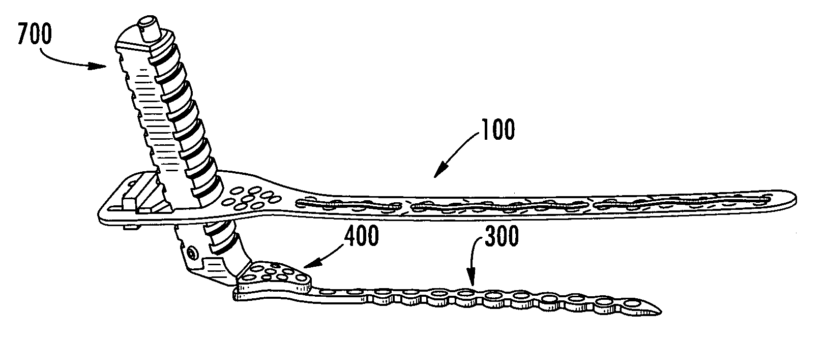
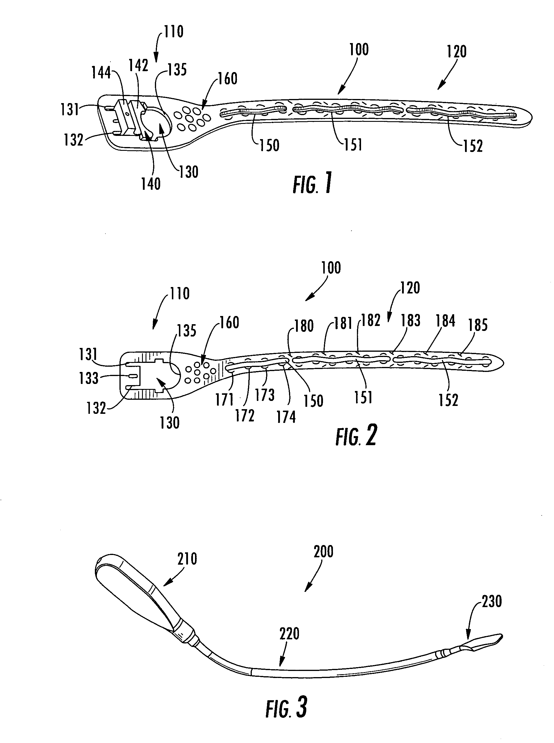
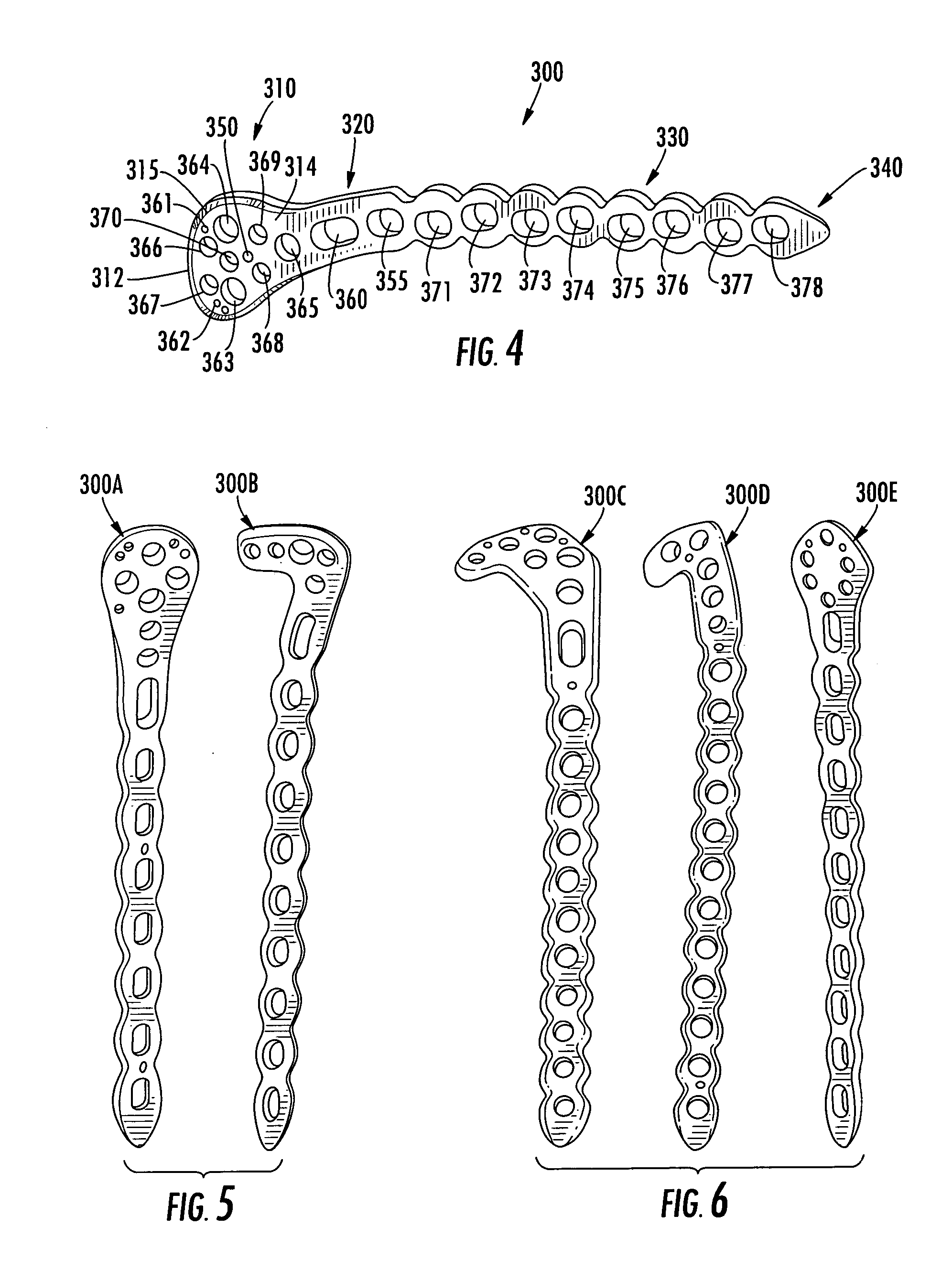
[0074] With reference to FIGS. 1, 2 and 19, there is illustrated a preferred embodiment of a trial component 100 of the present invention. The trial component 100 has a head 110 and a stem 120. The orientation of the head 110 versus the stem 120, and the general shape of the trial 100 approximates the shape of a bone plate 300 to be used on the distal femur, as is recognized by those skilled in the art. Trial 100 is intended to be used with a correspondingly shaped bone plate 300 for the distal femur. One side of the trial 100 is for use with the left femur while, when flipped over, the other side is for use with the right femur. Trial and bone plate shapes and sizes that correspond to other long bones are equally envisioned, and will be recognized by those skilled in the art.

[0075] The head 110 of the trial 100 has an opening 130 therethrough, and a slider 140 cooperatively assembled with the opening 130. The opening 130 has two extensions 131 and 132, a slot ...


PUM


Abstract

Bone plating implants, instruments, systems and methods for fracture fixation are provided. The systems includes the instruments and implants comprising a trial component, handle, aiming block, bone plate, tissue spreader, drill guide, K-wire guide, monoaxial screw-locking inserts, polyaxial screw-locking inserts, cable plugs, K-wires, monoaxial screws and polyaxial screws. The methods include the use of the instruments and implants for either open or minimally invasive fracture fixation surgery.

Description

BACKGROUND OF THE INVENTION [0001] The present invention relates to a bone plating system and instrumentation used in the fixation of fractures of long bones such as the femur, tibia, humerus and radius, including periarticular fractures. More specifically, the present invention encompasses a bone plating system that aids in preoperative planning of plate selection and placement, intraoperative adjustment and fixation of the plate to the fractured bone, as well as implementation in minimally invasive surgery, hereinafter referred to as MIS. [0002] Typical fixation of a fracture of a long bone with a bone plate requires making an incision in the tissue, reducing the fracture, placing a bone plate on the fractured bone, and securing the bone plate to the bone with fixation elements such as screws. The bone plate immobilizes the fracture and keeps the bone in a correct position so as to allow the fracture to heal. [0003] Typically, bone plates have a bone contacting side and a side fac...

Claims


Application Information

Patent Timeline
Patent Type & Authority Applications(United States)
IPC IPC(8): A61F2/30
CPCA61B17/02A61B17/1728A61B17/80A61B17/8042A61B17/8052A61B17/808A61F2002/4658A61B17/88A61B19/54A61B2017/00238A61B2017/0046A61B2017/00464A61F2/4684A61B17/842A61B90/39
Inventor LUTZ, CHRISTIANCROZET, YVESWIRTH, RENE
Owner STRYKER EURO OPERATIONS HLDG LLC
Why Eureka
Try Eureka