Portable pressure transducer, pneumotach for use therewith, and associated methods

a technology of pressure transducer and portability, which is applied in the direction of pressure difference measurement between multiple valves, instruments, diagnostic recording/measure, etc., can solve the problems of difficult precise estimation of wasted and inhaled portions of compression volume, significant difference between pressure, flow, and volume of gas, and the inability of pressure flow sensors to suffer deficiencies, etc., to achieve wide manufacturing tolerances, facilitate formation and maintenance, and reduce the cost of the pneumotach

Inactive Publication Date: 2006-06-08
RIC INVESTMENTS LLC
View PDF16 Cites 48 Cited by
  • Summary
  • Abstract
  • Description
  • Claims
  • Application Information

AI Technical Summary

Benefits of technology

[0019] A portable pressure transducer according to the present invention is configured to be operatively coupled to a pneumotach of the invention and, thus, may be carried upon a respiratory conduit. Either the pressure ports of the pneumotach or those of the sample conduits of the portable pressure transducer are substantially larger than the other so as to facilitate the formation and maintenance of a fluid-tight (e.g., airtight) seal without requiring precise alignment between all (typically two) of the pressure ports and their corresponding sample conduits. By configuring the pneumotach in this manner, wide manufacturing tolerances may be used, which decreases the cost of the pneumotach, thereby making the pneumotach more amenable to single patient use (i.e., disposability). Further, configuring one of the pneumotach and the portable pressure transducer with relatively loose tolerances facilitates the relatively easy assembly of these two structures. In addition to sample conduits that align with the pressure ports of the pneumotach, the portable pressure transducer may include valves that direct the flow of an individual's respiration therethrough and also includes one or more pressure sensors by which an individual's respiratory pressure is measured.

Problems solved by technology

Many known differential pressure flow sensors suffer deficiencies when exposed to less than ideal gas and flow inlet conditions and, further, possess inherent design problems with respect to their ability to sense differential pressure in a meaningful, accurate, repeatable manner over a substantially dynamic flow range.
Measurements of flow in this way may result in a substantial difference between the flow, pressure, and volume of gases that are delivered to or exhaled by the patient and that are reported by a pressure or flow sensor which is associated with the ventilator.
Even when a correction is applied, precise estimation of the wasted and inhaled portions of the compression volume is difficult because of variations between individual respiratory conduits, the use of humidifiers, the use of heat-moisture exchangers, and other circuit components.
The use of such small bore tubing is, however, somewhat undesirable from the standpoint that the pressure samples which are conveyed from the pneumotach may be damped or distorted as they travel through the tubing.
Additionally, the use of flow sensors with tubing in clinical environments, such as critical and intensive care where high humidity is often the norm, leads to the condensation of moisture in the pressure transmission tubing, whether or not the pressure transmission tubing or any portion of the respiratory conduit is heated.
One result of condensation is a damping and distortion of respiratory samples, or the pressure “signals”, that propagate down the pressure transmission tubes.
Typically, pressure transmission tubes are periodically purged with air from a compressed gas source or a pump in order to reduce the adverse effects of condensate on pressure and flow measurements, which creates additional work for healthcare personnel and, therefore, is a somewhat undesirable practice.
Additionally, accidental or intentional disconnection of the tubing from the monitor may cause condensate or even sputum to flow into the pressure transmission tubes and potentially contaminate the monitor.
Further, the lengthy tubing of conventional differential pressure flow sensors is typically discarded after use, resulting in a significant amount of plastic waste.
Accordingly, employing such tubing as a single-use element of a differential pressure flow sensor is costly.
Reuse of pressure transmission tubing is also typically contrary to manufacturer recommendations due to the potential for contamination of the pressure transducer, as well as the potential (although not significant) extubation hazard posed thereby in the clinical environment.

Method used


Image

  • Portable pressure transducer, pneumotach for use therewith, and associated methods
  • Portable pressure transducer, pneumotach for use therewith, and associated methods
  • Portable pressure transducer, pneumotach for use therewith, and associated methods

Examples


Embodiment Construction

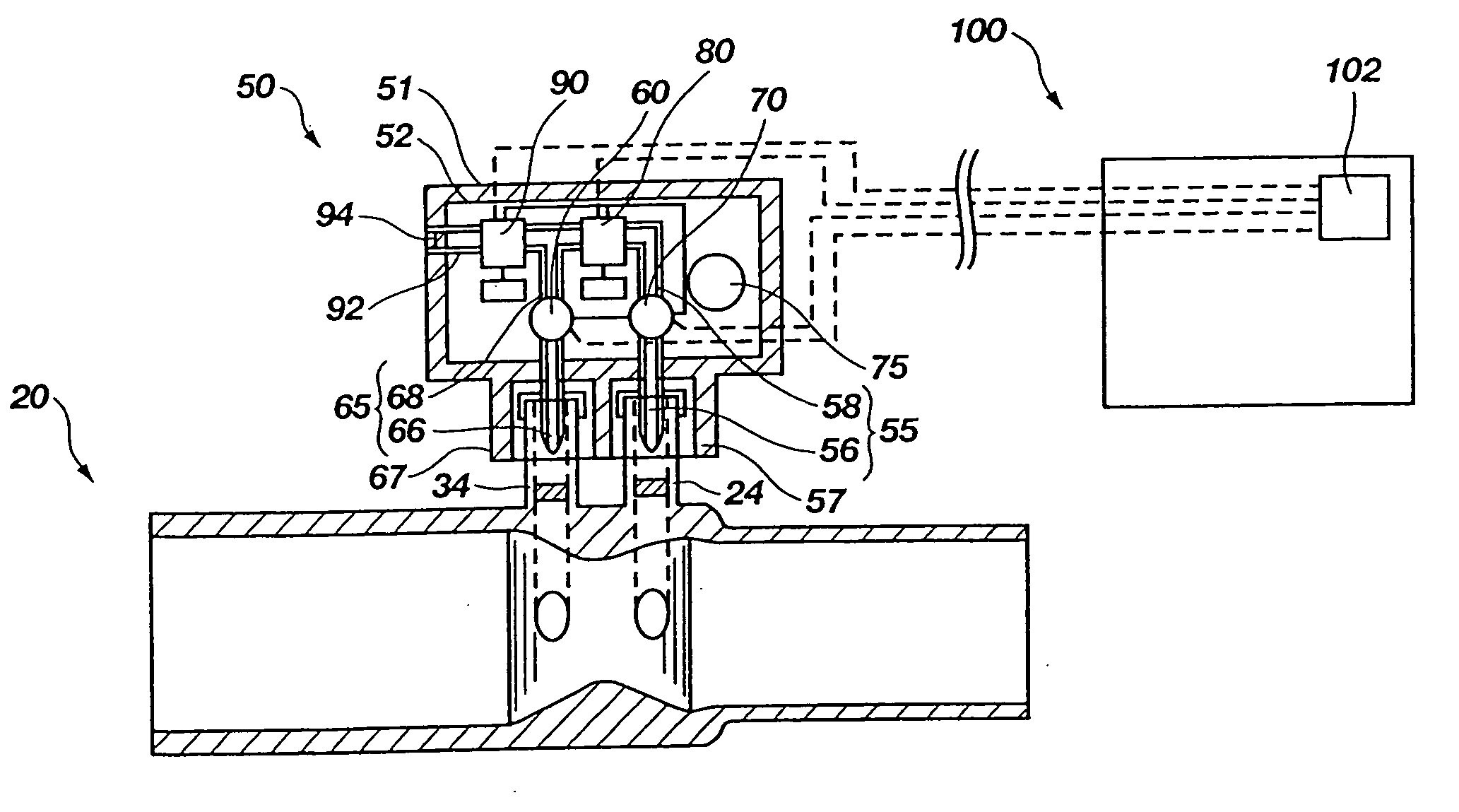
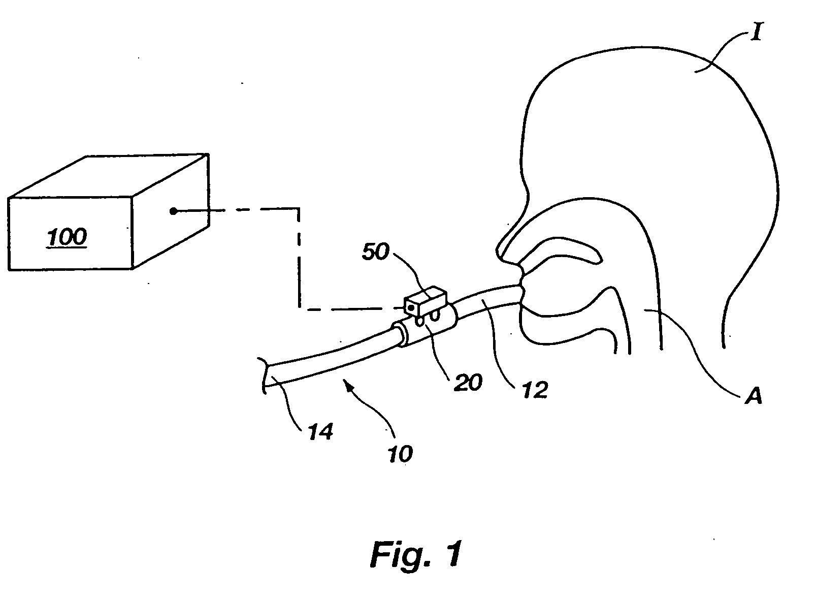
[0032] With reference to FIG. 1, a respiratory conduit 10 is depicted. Respiratory conduit 10 may comprise a breathing circuit which includes an endotracheal tube, a nasal canula, or any other conduit that is configured to communicate with the airway A of an individual I. As depicted, one end 12 of respiratory conduit 10 is placed in communication with airway A, while the other end 14 of respiratory conduit 10 opens to the atmosphere, a source of gas to be inhaled by individual I, or a ventilator, as known in the art. Positioned along its length, respiratory conduit 10 includes at least one airway adapter, in this case a pneumotach 20, which is a component of a type of pressure sensor. Also shown in FIG. 1 is a portable pressure transducer 50 coupled with and in flow communication with pneumotach 20. Portable pressure transducer 50 may, in turn, communicate electronically with a computer, such as a pressure or flow monitor 100, as known in the art.

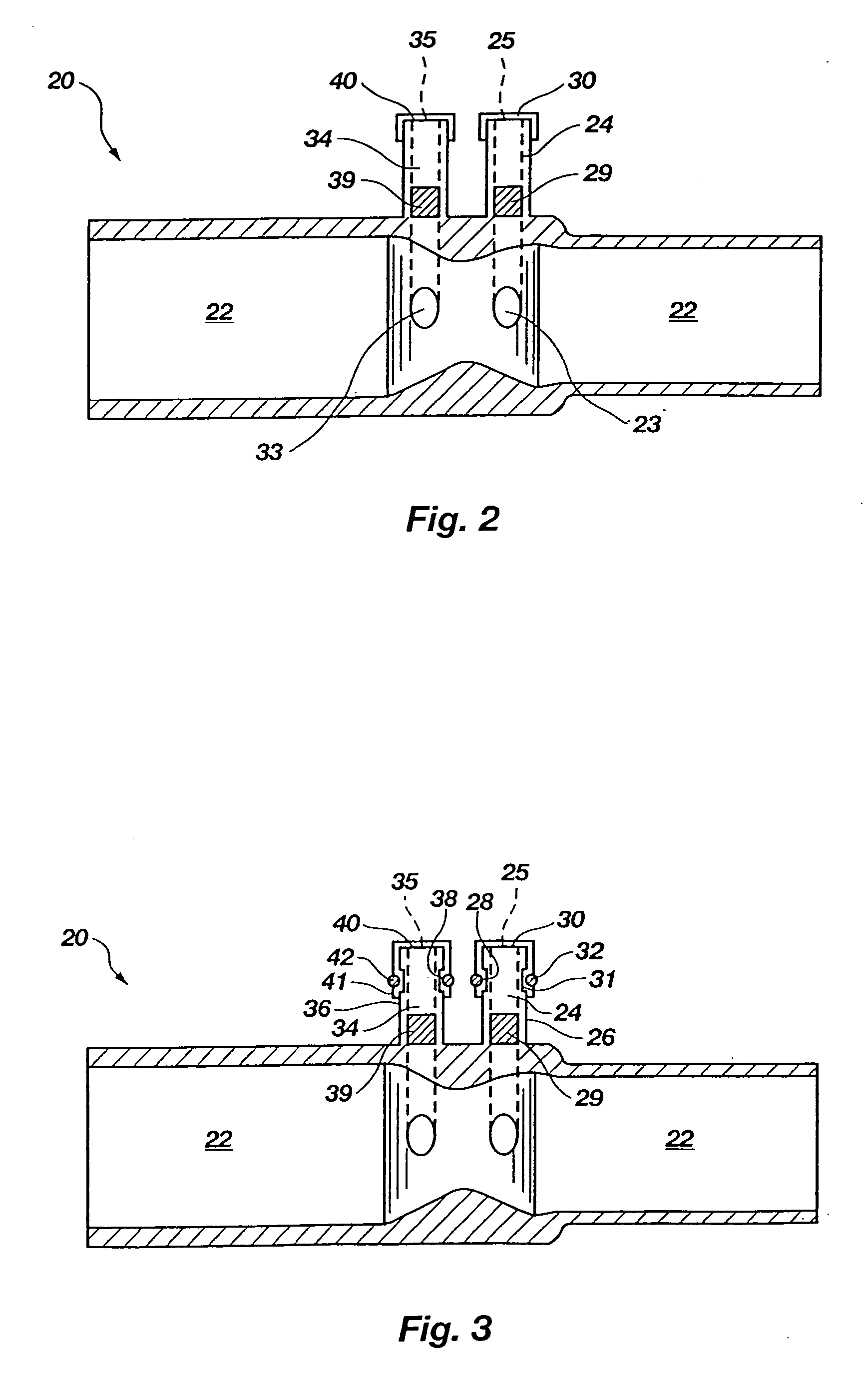
[0033] Referring now to FIG. 2, th...


PUM

PropertyMeasurementUnit
pressuresaaaaaaaaaa
pressureaaaaaaaaaa
pressureaaaaaaaaaa

Abstract

A system for sensing respiratory pressure includes a portable pressure transducer configured to be carried by or proximate to a respiratory conduit, such as a breathing circuit or a nasal canula. The portable pressure transducer may removably couple with a pneumotach, in the form of an airway adapter, disposed along the respiratory conduit. The pneumotach may include two pressure ports positioned at opposite sides of an obstruction, which partially blocks flow through a primary conduit of the pneumotach. Corresponding sample conduits of the portable pressure transducer removably couple with the pressure ports. The pressure ports may have sealing elements which are configured to seal against piercing members of the sample conduits upon introduction of the piercing members therethrough. Upon removal of the piercing members, the sealing elements substantially reseal. Methods for using the system are also disclosed.

Description

CROSS-REFERENCE TO RELATED APPLICATION [0001] This application is a Continuation under 35 U.S.C. § 120 of U.S. patent application Ser. No. 10 / 729,404 filed Dec. 5, 2003, which is a Divisional under 35 U.S.C. § 120 of U.S. patent application Ser. No. 10 / 139,920 filed May 7, 2002, which claims the benefit under the provisions of 35 U.S.C. § 119(e) of U.S. Provisional application Ser. No. 60 / 289,540, filed on May 7, 2001.BACKGROUND OF THE INVENTION [0002] 1. Field of the Invention [0003] The present invention relates generally to apparatus for measuring respiratory pressure or flow and, more specifically, to respiratory pressure transducers. More particularly, the present invention relates to pressure transducers which may be positioned proximate to a respiratory conduit which is configured to communicate with the airway of an individual. [0004] 2. Background of Related Art [0005] Respiratory flow measurement during the administration of anesthesia, in intensive care environments, and ...

Claims


Application Information

Patent Timeline
Patent Type & Authority Applications(United States)
IPC IPC(8): G01L7/00A62B9/00A61B5/08A61B5/087G01F1/00G01F1/36
CPCA61B5/087G01L13/00
Inventor ORR, JOSEPH A.KOFOED, SCOTT A.DURST, KEVIN
Owner RIC INVESTMENTS LLC
Why Eureka
Try Eureka