Holographically encoded elements for microarray and other tagging labeling applications, and method and apparatus for making and reading the same

a technology of optical elements and holographic encoders, applied in the field of method and apparatus for writing a code on an optical element, can solve the problem of limiting the type of applications in which the coded optical element may be used

Active Publication Date: 2006-06-08
ILLUMINA INC
View PDF99 Cites 35 Cited by
  • Summary
  • Abstract
  • Description
  • Claims
  • Application Information

AI Technical Summary

Problems solved by technology

However, the known ways involve writing a code that is linear which limits the amount of information that can be contained in such a code, which in turn limits the type of applications in which the coded optical elements may be used.

Method used


Image

  • Holographically encoded elements for microarray and other tagging labeling applications, and method and apparatus for making and reading the same
  • Holographically encoded elements for microarray and other tagging labeling applications, and method and apparatus for making and reading the same
  • Holographically encoded elements for microarray and other tagging labeling applications, and method and apparatus for making and reading the same

Examples


Embodiment Construction

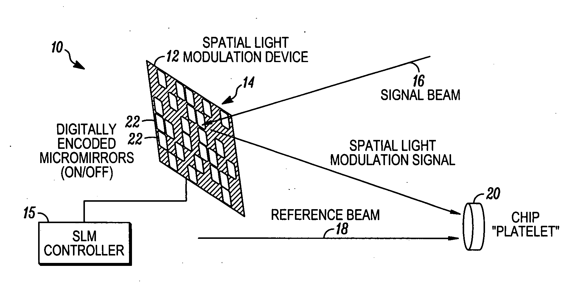
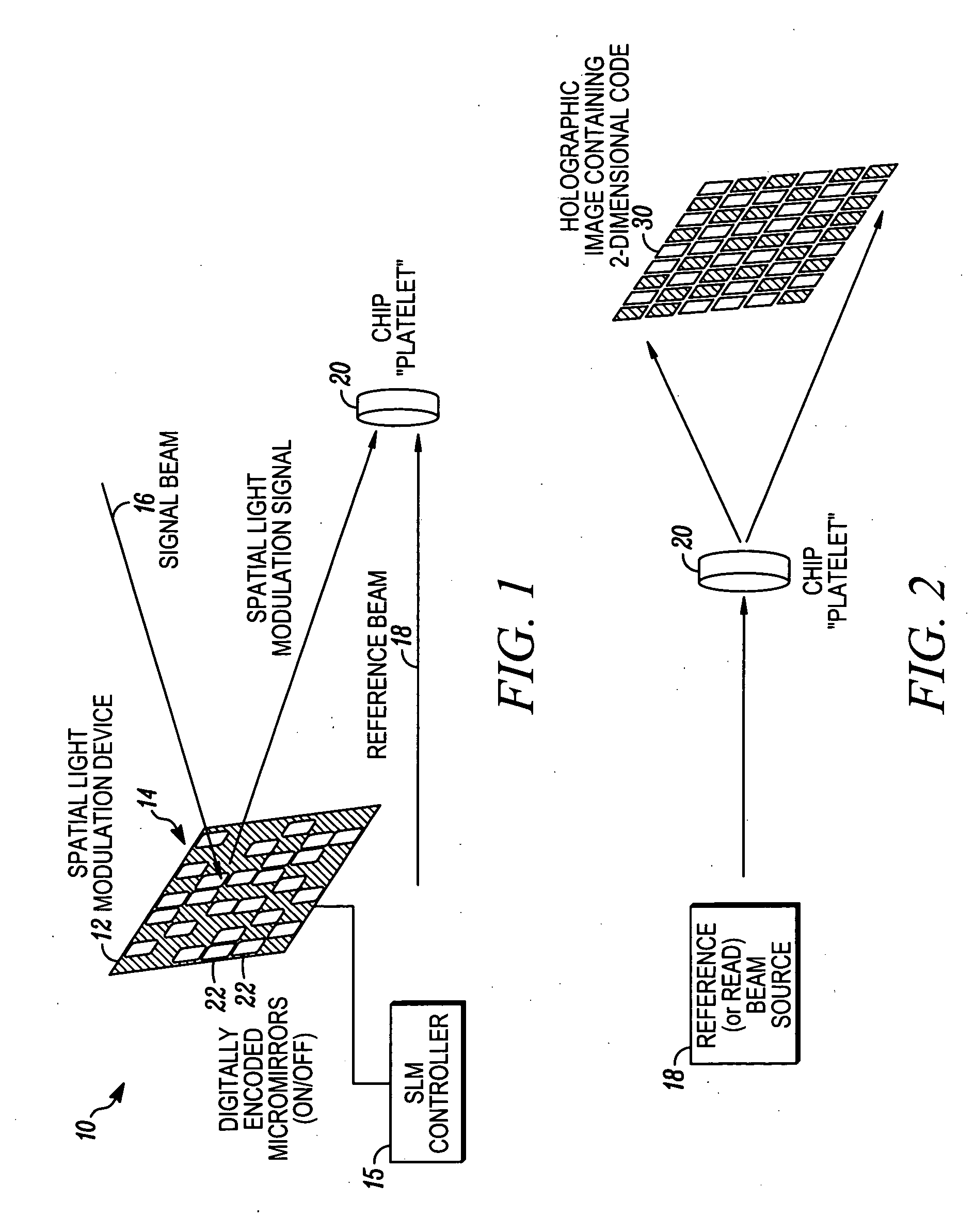
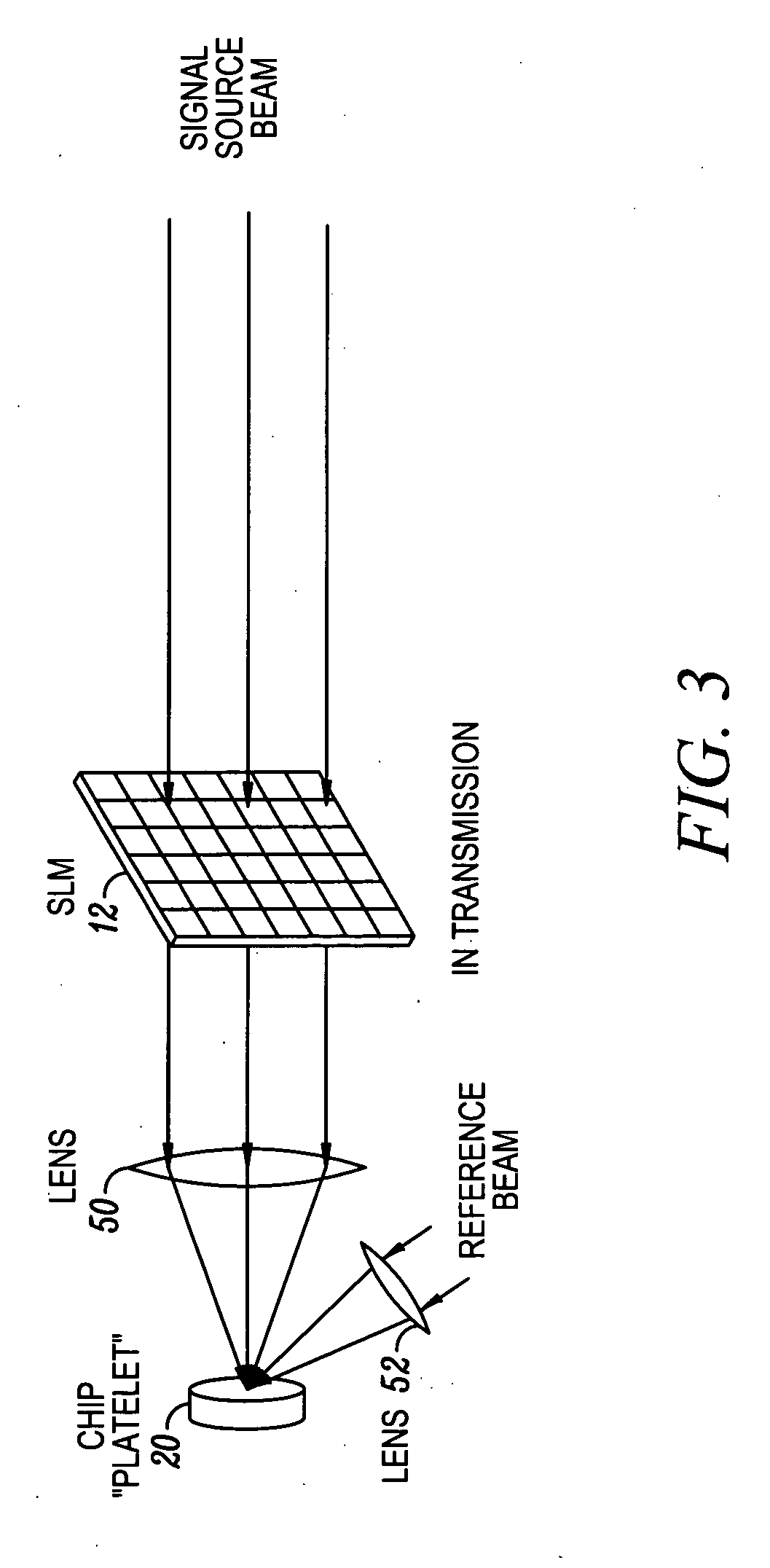
[0032]FIG. 1 shows the apparatus generally indicated as 10 for writing a code on an optical element. The apparatus 10 includes a spatial light modulation device 12 having an n-dimensional code generally indicated as 14 configured or programmed thereon that responds to the signal beam 16, for providing a spatial light modulation signal containing the n-dimensional code 14; as well as a reference beam. The spatial light modulator 12 is arranged in relation to an optical element 20 so that the interference pattern generated between the spatial light modulation signal and the reference beam is written on or in the optical element 20 as a holographic image of the n-dimensional code 14. After the holographic image of the n-dimensional code 14 is written on or in the optical element, it takes the form of a holographically encoded optical element 20 having such an n-dimensional code. In FIG. 1, the n-dimensional code on the spatial light modulation device 12 is shown in the form of a 2-dime...


PUM


Abstract

A method and apparatus is provided for writing a code on an optical element, wherein the code is written on the optical element in the form of a holographic image of an n-dimensional code generated by an interference pattern between a reference beam and a signal beam reflected off a spatial light modulation device having the n-dimensional code configured thereon. The method includes steps of generating the interference pattern between the reference beam and the signal beam reflected off the spatial light modulation device having the n-dimensional code thereon; as well as writing the interference pattern on the optical element as a holographic image of the n-dimensional code.

Description

CROSS REFERENCES TO RELATED APPLICATIONS [0001] This application claims benefit to provisional patent application No. 60 / 628,827 (WFVA / CyVERA nos. 714-1.8 / CV 28PR), filed Nov. 16, 2004, which is hereby incorporated by reference in their entirety. [0002] The following cases contain subject matter related to that disclosed herein and are incorporated herein by reference in their entirety: U.S. patent application Ser. No. 10 / 661,234 (CyVera Docket No. CV-0038A), filed Sep. 12, 2003, entitled “Diffraction Grating-Based Optical Identification Element”; U.S. patent application Ser. No. 10 / 661,031 (CyVera Docket No. CV-0039A) filed Sep. 12, 2003, entitled “Diffraction Grating-Based Encoded Micro-particles for Multiplexed Experiments”; U.S. patent application Ser. No. 10 / 661,082 (CyVera Docket No. CV-0040), filed Sep. 12, 2003, entitled “Method and Apparatus for Labeling Using Diffraction Grating-Based Encoded Optical Identification Elements”; U.S. patent application Ser. No. 10 / 661,115 (Cy...

Claims


Application Information

Patent Timeline
Patent Type & Authority Applications(United States)
IPC IPC(8): G06K7/10
CPCG06K7/10663
Inventor KERSEY, ALAN D.MOON, JOHN A.PUTNAM, MARTIN A.
Owner ILLUMINA INC
Why Eureka
Try Eureka