Media for detection of X-ray exposure
a technology for x-ray exposure and media, applied in the field of x-ray detection devices, can solve the problems of reducing requiring very large x-ray doses, and affecting the detection efficiency of x-ray radiation,
- Summary
- Abstract
- Description
- Claims
- Application Information
AI Technical Summary
Benefits of technology
Problems solved by technology
Method used
Image
Examples
example 1
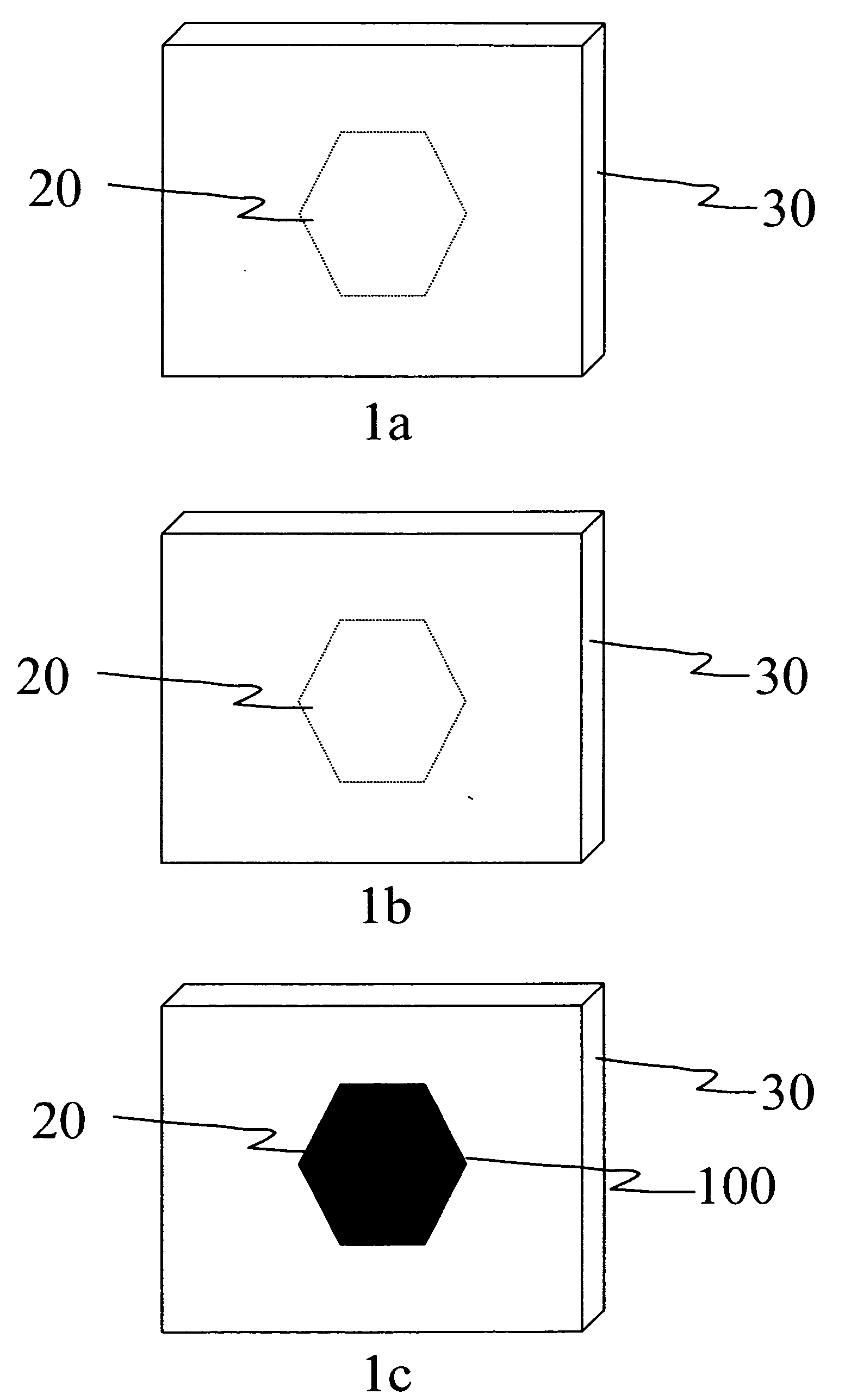
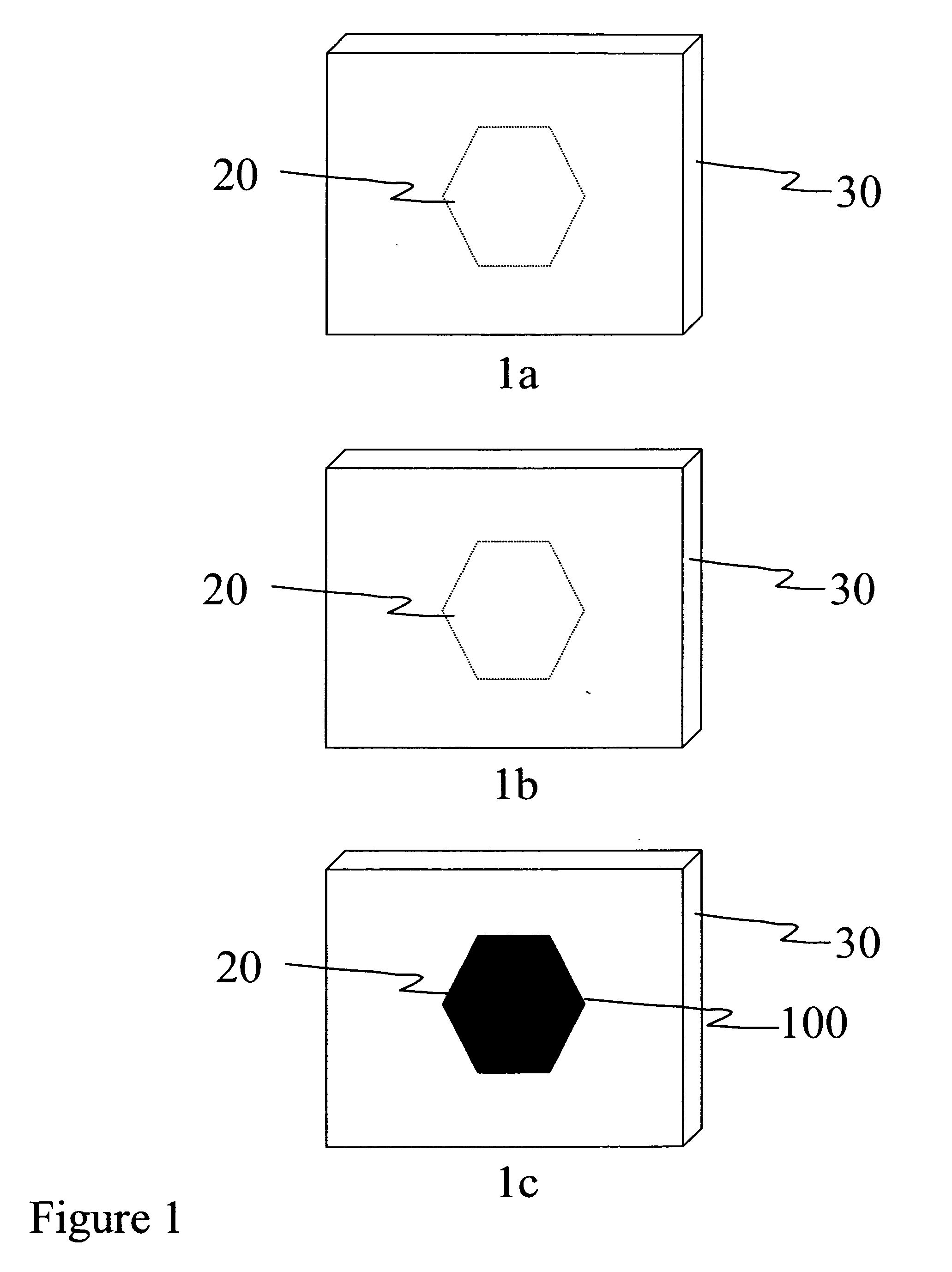
[0030] Inorganic materials were exposed to an X-ray beam for specified time and defined X-ray source voltage and current settings. These materials showed a color change as detailed in Table 1.
TABLE 1Effect of X-ray Exposure on X-ray Sensitive Inorganic MaterialsMaterialX-rayColorMaterialX-raySourceBeforeColor AfterX-raySourceCurrentExposureX-rayX-rayMaterialSourceKilovoltsMilliampsTimeExposureExposurePotassiumX-ray tube75401 minuteWhitePurplechloridePotassiumX-ray tube75403 minutesWhitePurplechlorideSodiumX-ray tube75401 minuteWhiteLight BluebromideSodiumX-ray tube75401 minuteWhiteGoldenchlorideYellowPotassiumX-ray tube75401 minuteWhiteGreeniodideZirconiumRotating503001 minuteWhiteBlackoxideAnodeZirconiumRotating503005 minutesWhiteBlackoxideAnodeSodiumRotating503005 minutesWhiteLight PinkBicarbonateAnodeSilverRotating503003 minutesWhiteBrownSulfideAnodeTin OxideRotating503005 minutesLight GrayDark GrayAnode
[0031] All materials in Table 1 showed a color change upon X-ray exposure w...
example 2
[0034] Organic materials were exposed to an X-ray beam for specified time and defined X-ray source voltage and current settings. These materials showed a color change as detailed in Table 2.
TABLE 2Effect of X-ray Exposure on X-ray Sensitive Organic MaterialsMaterialX-rayColorMaterialX-raySourceBeforeColor AfterX-raySourceCurrentExposureX-rayX-rayMaterialSourceKilovoltsMilliampsTimeExposureExposureHTDX-ray tube75402 minuteWhiteDark PinkCIN 10082837CD2X-ray tube75403 minutesWhiteDark Pink
[0035] All materials in Table 2 showed a color change upon X-ray exposure without any chemical or physical processing steps. All materials in Table 2 do not show a color change upon exposure to ambient light, including ultraviolet light.
example 3
[0038] Polymeric materials were exposed to an X-ray beam for specified time and defined X-ray source voltage and current settings. These materials showed a color change as detailed in Table 3.
TABLE 3Effect of X-ray Exposure on X-ray Sensitive Polymeric MaterialsMaterialX-rayColorMaterialX-raySourceBeforeColor AfterX-raySourceCurrentExposureX-rayX-rayMaterialSourceKilovoltsMilliampsTimeExposureExposure5 minuteX-ray tube7540 1 secondClearYellow-DevconorangeEpoxy5 minuteX-ray tube7540 5 secondsClearYellow-DevconorangeEpoxy5 minuteX-ray tube754010 secondsClearYellow-DevconorangeEpoxy5 minuteX-ray tube754015 secondsClearYellow-DevconorangeEpoxy
[0039] The materials in Table 3 showed a color change upon a wide range of X-ray exposure times without any chemical or physical processing steps. All materials in Table 3 do not show a color change upon exposure to ambient light, including ultraviolet light.
PUM
 Abstract
Description
Claims
Application Information
 - R&D
- Intellectual Property
- Life Sciences
- Materials
- Tech Scout
- Unparalleled Data Quality
- Higher Quality Content
- 60% Fewer Hallucinations
Browse by: Latest US Patents, China's latest patents, Technical Efficacy Thesaurus, Application Domain, Technology Topic, Popular Technical Reports.
© 2025 PatSnap. All rights reserved.Legal|Privacy policy|Modern Slavery Act Transparency Statement|Sitemap|About US| Contact US: help@patsnap.com


