Magnetic head slider with reduced bearing surface area and magnetic disk drive

Inactive Publication Date: 2006-06-08
WESTERN DIGITAL TECH INC
View PDF4 Cites 11 Cited by
  • Summary
  • Abstract
  • Description
  • Claims
  • Application Information

AI Technical Summary

Benefits of technology

[0026] According to the present invention, a pressing load to the compact slider can be increased by about 1.5 times as large as that o

Problems solved by technology

(1) The air bearing stiffness decreases, which degrades the flying characteristic of the slider.
Thus, the flying height in a pitch direction severely fluctuates with disturbance vibra

Method used


Image

  • Magnetic head slider with reduced bearing surface area and magnetic disk drive
  • Magnetic head slider with reduced bearing surface area and magnetic disk drive
  • Magnetic head slider with reduced bearing surface area and magnetic disk drive

Examples


Embodiment Construction

[0042] Specific embodiments of the present invention will be described in detail with reference to FIGS. 1 through 12. Various technically preferable restrictions are imposed on the preferred embodiments of the present invention to be described in the following. It should be noted, however, that the present invention is not limited to these embodiments and can be implemented in various manners without departing from the scope thereof.

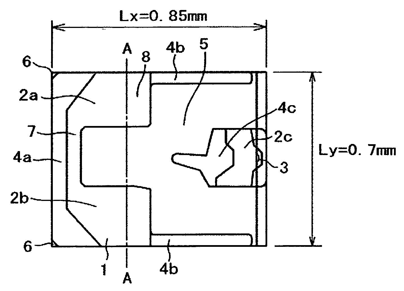
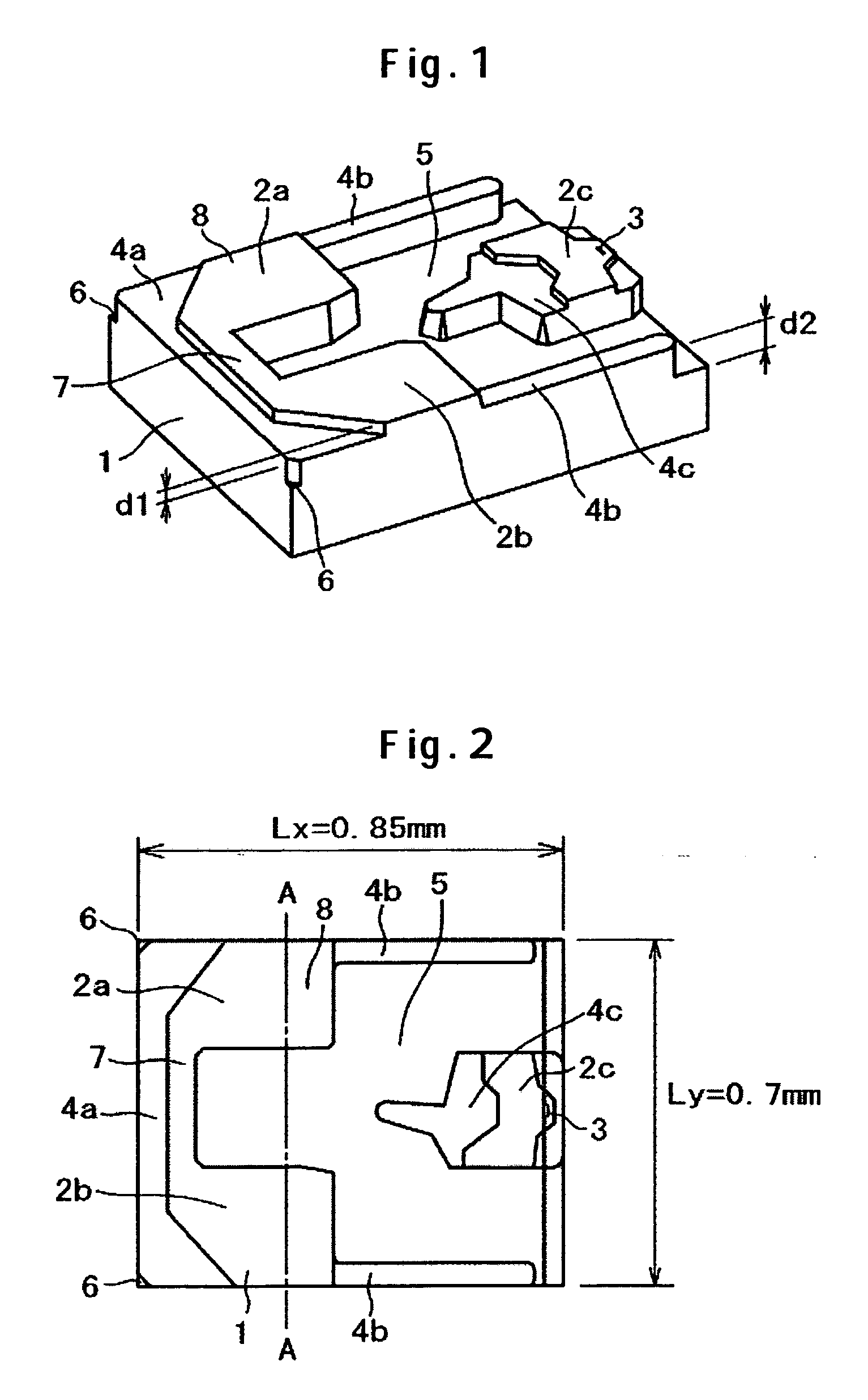
[0043]FIG. 1 is a perspective view of a magnetic head slider according to a first embodiment of the present invention. FIG. 2 is a plan view of the magnetic head slider. Referring to FIGS. 1 and 2, the magnetic head slider according to the first embodiment of the present invention is constructed as below so as to generate a lifting force by making use of an air bearing effect. Specifically, an inflow side shallowly grooved surface 4a is disposed on an inflow side of a medium opposing surface (bearing surface) of a slider 1. Further, a pair of inflow si...


PUM


Abstract

A compact slider has a reduced area of bearing surfaces, thus substantially decreasing a lifting force obtained through an air bearing characteristic. In one embodiment, a shallowly grooved surface and air bearing surfaces are disposed on an inflow side of a bearing surface of a slider. The air bearing surfaces are connected to each other through a connection air bearing surface. Side shallowly grooved surfaces are respectively disposed rearward of the air bearing surfaces. The side shallowly grooved surface extends up to a point near an outflow end. A center air bearing surface is disposed on the outflow end of the slider. A magnetic head is mounted on the center air bearing surface. A center shallowly grooved surface is disposed on an inflow side of the center air bearing surface. A deeply grooved surface is disposed at a center of the bearing surface. No cutting margins are provided on both sides of the slider. The air bearing surfaces on the inflow side therefore reach end faces in a width direction of the slider.

Description

CROSS-REFERENCES TO RELATED APPLICATIONS [0001] This application claims priority from Japanese Patent Application No. JP2004-350847, filed Dec. 3, 2004, the entire disclosure of which is incorporated herein by reference. BACKGROUND OF THE INVENTION [0002] The present invention relates generally to a magnetic head slider flying at a small distance above, or coming into intermittent contact with, the surface of a traveling recording medium and a magnetic disk drive. More specifically, the present invention relates to a magnetic head slider suitable for a magnetic disk drive using a small-diameter disk having a diameter of 45.7 mm (1.8 in.) or less. [0003] The magnetic head slider is supported by a flexure attached to a suspension. The magnetic head slider flies at a small distance above, or comes into intermittent contact with, a magnetic disk to write and read data thereto and therefrom. Patent Document 1 (Japanese Patent Laid-Open No. 2003-123422) discloses the magnetic head slider ...

Claims


Application Information

Patent Timeline
IPC IPC(8): G11B5/60
CPCG11B5/6005G11B5/6082
Inventor TAKEUCHI, YOSHINORIKOHIRA, HIDEKAZU
Owner WESTERN DIGITAL TECH INC
Why Eureka
Try Eureka