Circuit component module, electronic circuit device, and method for manufacturing the circuit component module
a technology of electronic circuit and component module, which is applied in the direction of printed circuit aspects, conductive pattern formation, electrical apparatus construction details, etc., can solve the problems of reducing the number and affecting the quality of components. , to achieve the effect of reducing the number of parts, enhancing the thermal conductivity, and reducing the number of heat-releasing plates for each electronic componen
- Summary
- Abstract
- Description
- Claims
- Application Information
AI Technical Summary
Benefits of technology
Problems solved by technology
Method used
Image
Examples
first embodiment
[0041] A circuit component module according to a first embodiment of the present invention and a method for manufacturing the same will now be described with reference to the drawings.
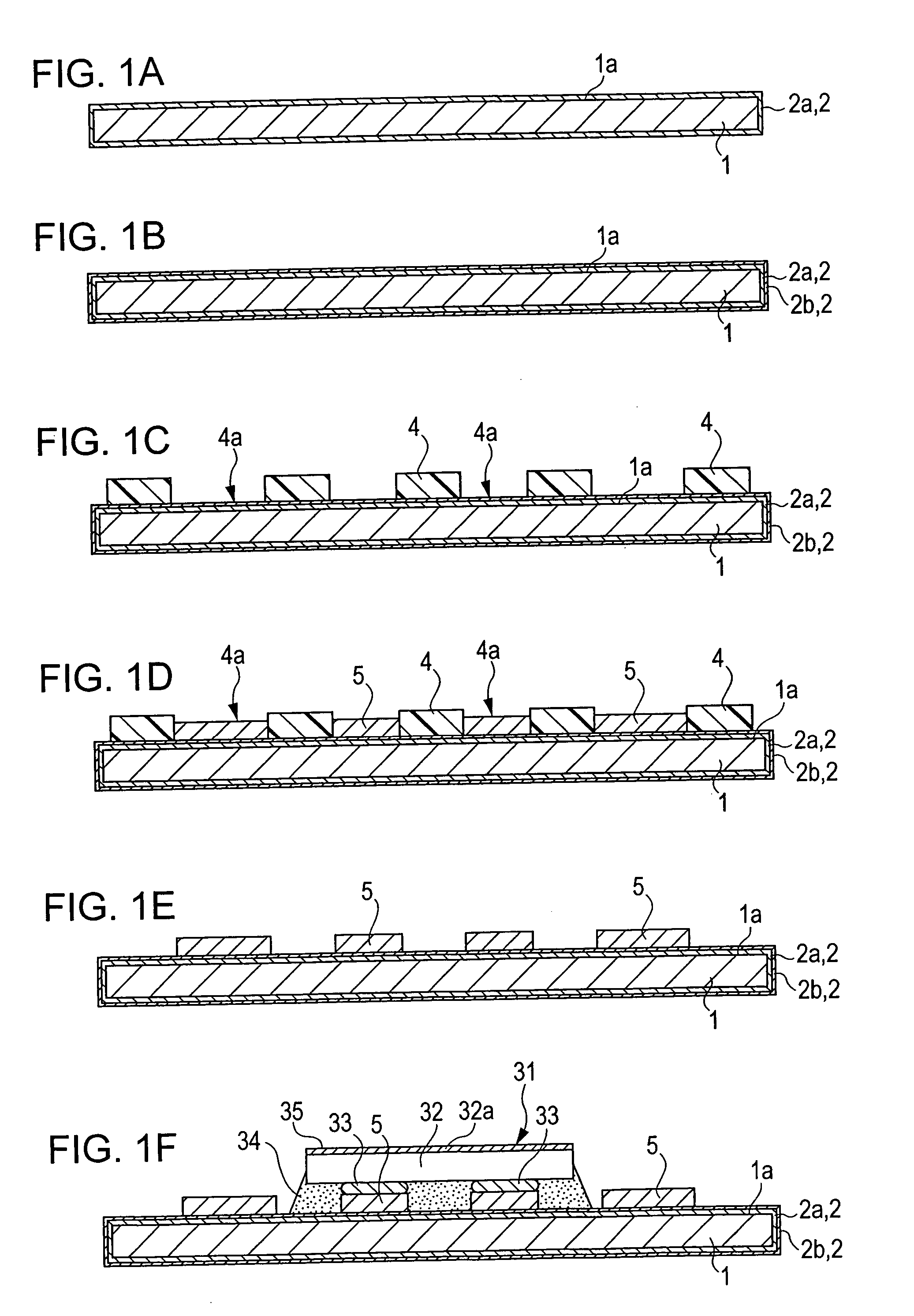
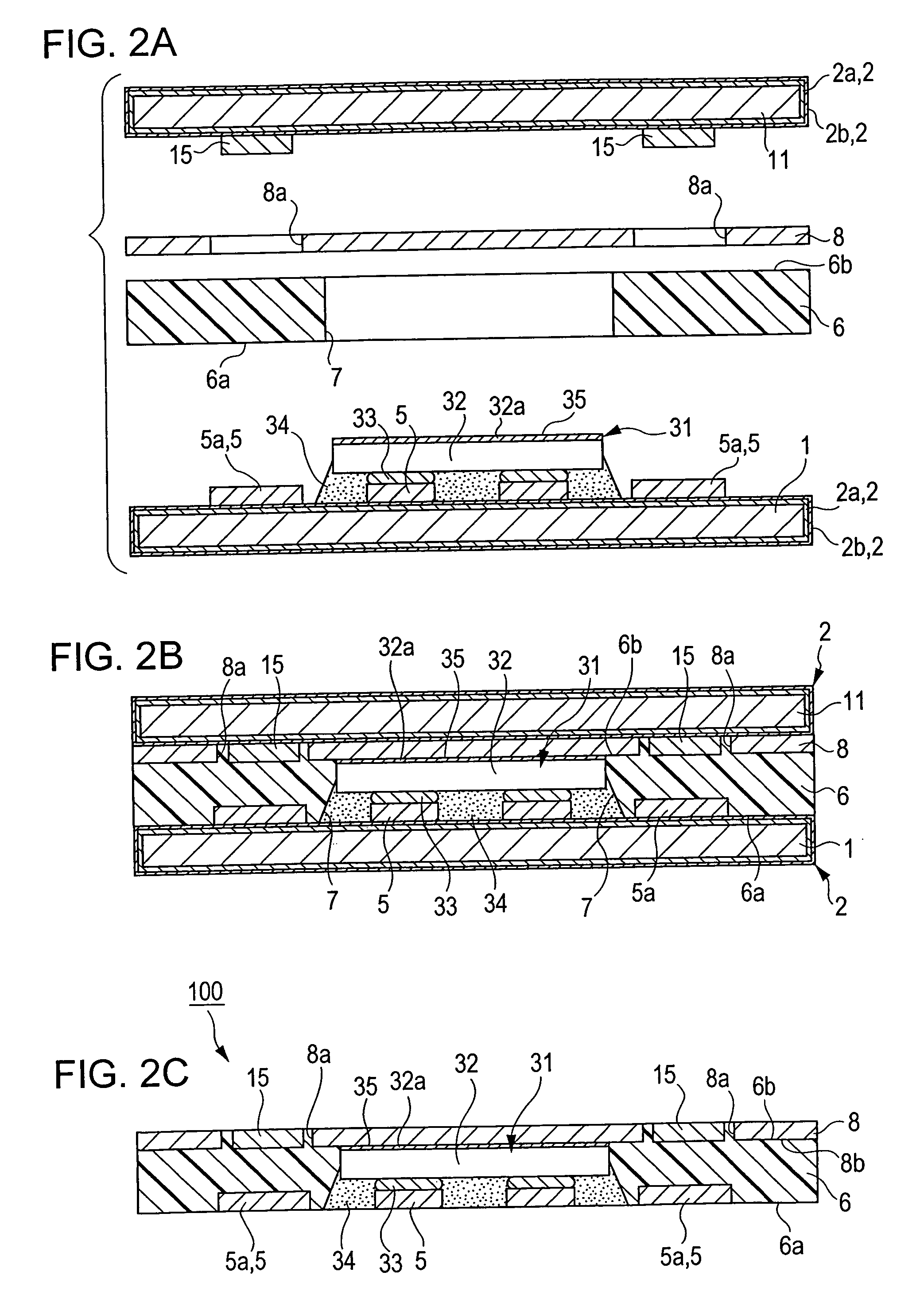
[0042] In the present embodiment, the method for manufacturing a circuit component module includes the mounting step of forming a seed layer and a wiring pattern on a base plate and mounting an electronic component on the base plate; the stacking step of stacking a first resin film and a heat-releasing plate on the base plate; and the removal step of removing the base plate and the seed layer.
[0043] In the mounting step, a seed layer is deposited on a base plate, and a wiring pattern is formed on the seed layer. Subsequently, an electronic component is mounted on the wiring pattern. In the stacking step, a first resin film having a pass-through hole and a heat-releasing plate are stacked on the base plate so that the electronic component is housed in the pass-through hole. In the removal step, the ba...
second embodiment
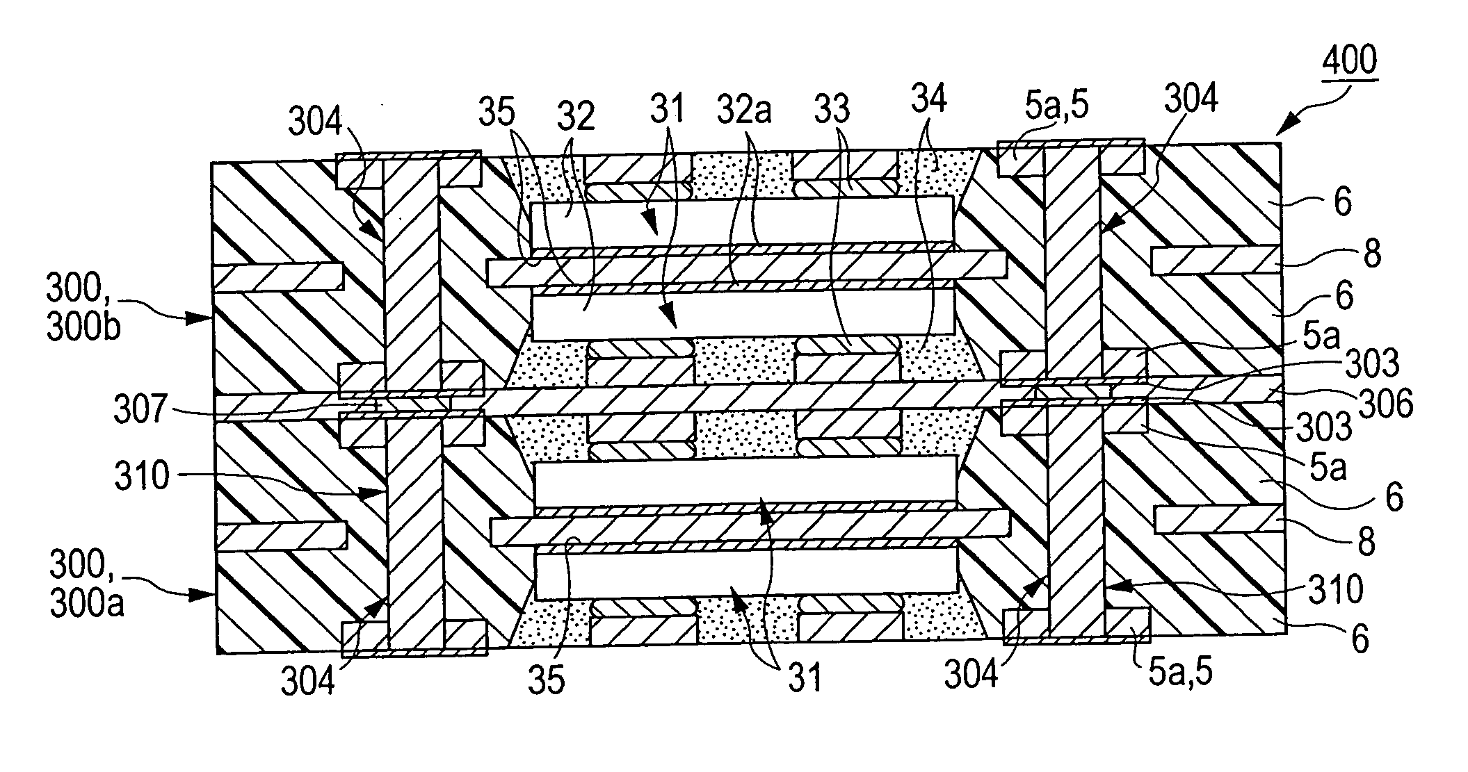
[0083] A circuit component module unit and its manufacturing method according to a second embodiment of the present invention will now be described. FIGS. 4A to 4C show a stacking step and a removal step of the method. The drawings referred to in the present embodiment are intended to illustrate the circuit component module and its manufacturing method, but do not necessarily correctly show its dimensional proportions according to the dimensions of the circuit component module unit used in practice.
Method for Manufacturing a Circuit Component Module Unit:
[0084] First, two base plates 1, two first resin films 6, and heat-releasing plate 8 are prepared as shown in FIG. 4A.
[0085] The base plate 1, which is the same as in the first embodiment, is coated with the seed layer 2 and has a wiring pattern 5 and the power IC 31. The first resin film 6 is a thermoplastic resin or glass epoxy plate with a thickness of about 100 to 500 μm, and has a pass-through hole 7. The heat-releasing pla...
third embodiment
[0100]FIG. 6 is a schematic sectional view of an electronic circuit device 500 according to a third embodiment. This electronic circuit device 500 includes the circuit component modules 100 of the first embodiment, and the first resin films 6 of the circuit component modules 100 are opposed to each other with the second resin film 106 therebetween. These resin films are bonded together to be integrated. Each circuit component module 100 has a heat-releasing plate 508 with a thickness of about 20 to 500 μm, doubling as an armoring plate. The heat-releasing plate 508 is bonded to the heat-releasing portion 32a of the power IC 31 with a thermally conductive adhesive 35.
[0101] The electronic circuit device 500 has the heat-releasing plates 508 doubling as the armoring plates that block external radio waves for signals transmitted through the wiring pattern 5 or a radiated electromagnetic field of the signals. In the electronic circuit device 500, the heat-releasing plates 508, the firs...
PUM
| Property | Measurement | Unit |
|---|---|---|
| thickness | aaaaa | aaaaa |
| thickness | aaaaa | aaaaa |
| thickness | aaaaa | aaaaa |
Abstract
Description
Claims
Application Information
 - R&D
- Intellectual Property
- Life Sciences
- Materials
- Tech Scout
- Unparalleled Data Quality
- Higher Quality Content
- 60% Fewer Hallucinations
Browse by: Latest US Patents, China's latest patents, Technical Efficacy Thesaurus, Application Domain, Technology Topic, Popular Technical Reports.
© 2025 PatSnap. All rights reserved.Legal|Privacy policy|Modern Slavery Act Transparency Statement|Sitemap|About US| Contact US: help@patsnap.com


