
Adjustment device and adjustment method for a tomography apparatus

a technology of tomography and adjustment device, which is applied in the field of adjustment device for tomography apparatus, can solve the problem that the correct alignment between the patient support device and the acquisition system cannot be implemented, and achieve the effect of precise but nevertheless simple alignment of the patient support devi

Inactive Publication Date: 2006-06-08
SIEMENS AG
View PDF14 Cites 8 Cited by
  • Summary
  • Abstract
  • Description
  • Claims
  • Application Information

AI Technical Summary

Benefits of technology

[0008] An object of the present invention is to provide a tomography apparatus and a method for aligning a tomography apparatus of the above type wherein that a more precise but nevertheless simple alignment of a patient support device and an acquisition system relative to one another is ensured.
[0010] The reference laser and the acquisition system thus are directly mechanically coupled with one another via the rotary frame such that a precise alignment of the laser beam relative to the acquisition plane is possible within slight tolerances. Tolerances arising from an indirect connection between the reference laser and the acquisition system, as occur, for example, by arrangement of the reference laser on a pivotable or movable frame associated with the stationary part of the tomography apparatus, are prevented.
[0014] In an embodiment of the invention, the reference laser generates a laser fan. A projection of the laser fan as a reference for the direction perpendicular to the acquisition plane enables a simple and fast monitoring of the position of the patient support device. For example, if the reference laser projects a laser fan onto a reference element in the form of a marking line, an offset of the position between patient support device and acquisition system can be optically detected in a reliable and simple manner by detecting deviation of the projection from the marking line.
[0016] At least one mounting bracket for mounting of a spirit level is provided on the rotary frame, such that the rotation angle positions of the reference laser can be very precisely adjusted.

Problems solved by technology

If the laser beam generated by the reference laser is not situated perpendicularly to the acquisition plane of the acquisition system, a correct alignment between the patient support device and the acquisition system cannot be implemented.

Method used


Image

  • Adjustment device and adjustment method for a tomography apparatus
  • Adjustment device and adjustment method for a tomography apparatus
  • Adjustment device and adjustment method for a tomography apparatus

Examples


Embodiment Construction

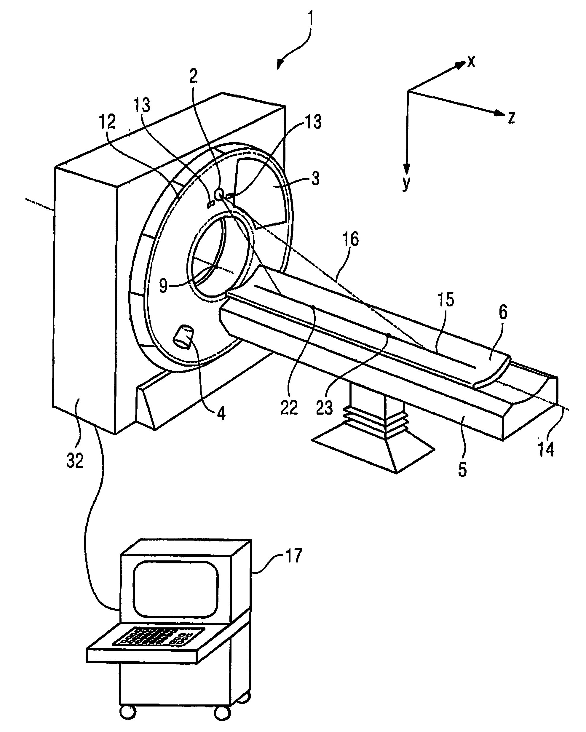
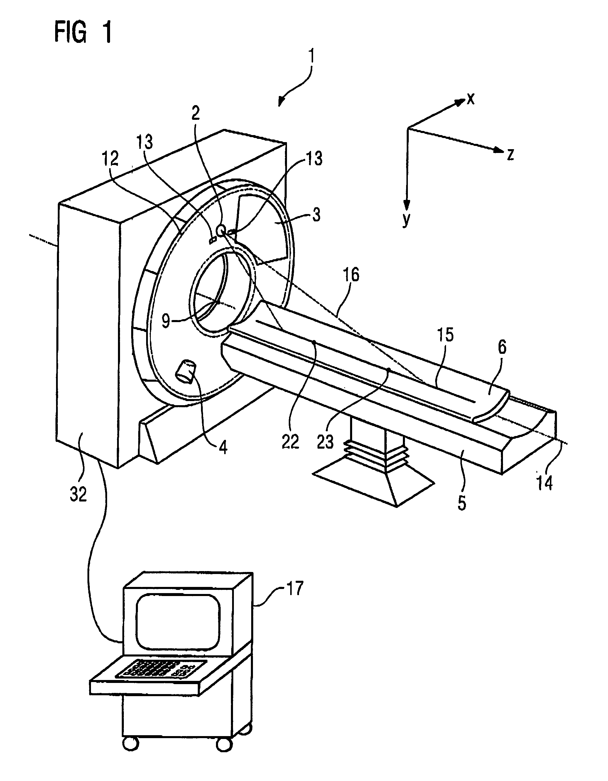
[0044] An inventive tomography apparatus (here in the form of a computed tomography apparatus 1) is shown in FIG. 1 in a perspective view. The computed tomography apparatus 1 has a patient support device, formed by a base 5 and a table plate 6, for supporting a subjects for example a patient, an acquisition system, formed by an x-ray radiation 4 and a radiation detector 3, arranged on a rotary frame 12, calculation unit (computer) 17 for reconstruction of slice and volume images and an adjustment device for mutual alignment of the patient support device and of the acquisition system.

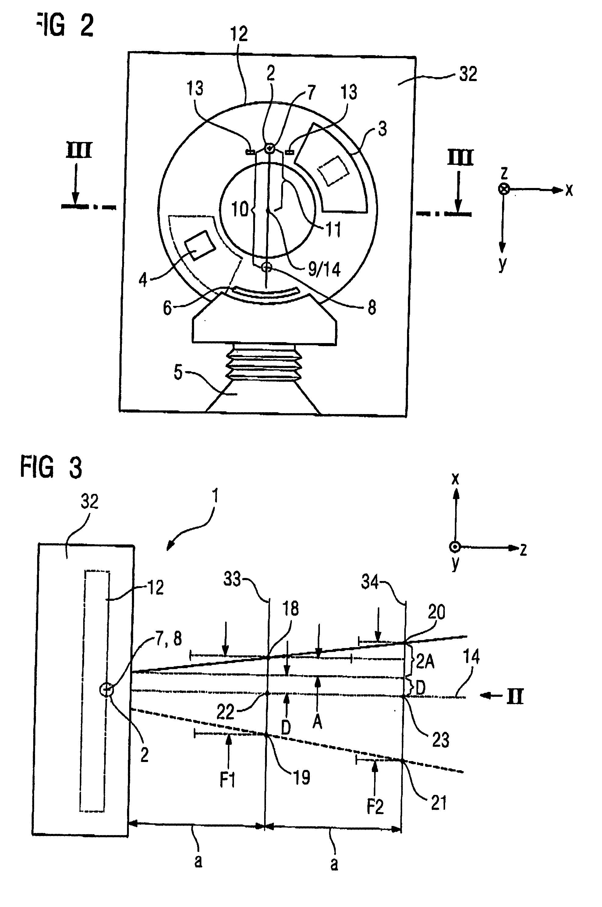
[0045] The adjustment device is formed by two components, namely a reference laser 2 and a reference element 15. The reference laser 2 is arranged directly on the rotary frame 12 and thus is in direct mechanical connection with the acquisition system 3, 4. In this example, the reference laser 2 is arranged on the rotary frame 12 in addition to the radiation detector 3 of the acquisition system. In princ...


PUM


Abstract

In an adjustment device and method for a tomography apparatus for aligning of a patient support device and an acquisition system relative to one another, a reference laser projects onto a reference element associated with the patient support device, the reference laser being directly associated with a rotary frame of the acquisition system, such that tolerances in the alignment between the reference laser and the acquisition system are prevented. Moreover, due to the arrangement of the reference laser directly on the rotary frame of the tomography apparatus, a simple calibration between laser beam and the acquisition plane of the acquisition system is ensured by a displacement of the reference laser in two different rotation angle positions which exhibit an angular interval therebetween of substantially 180 degrees.

Description

BACKGROUND OF THE INVENTION [0001] 1. Field of the Invention [0002] The present invention concerns an adjustment device for a tomography apparatus for alignment of a patient support device and an acquisition system relative to one another, of the type wherein the acquisition system can rotate around a system axis on a rotary frame, and wherein the adjustment device has a reference element assigned to the patient support device and a reference laser projecting on the reference means. The invention also concerns a method for aligning a patient support device and an acquisition system relative to one another. [0003] 2. Description of the Prior Art [0004] An adjustment device and an adjustment method of the above type are known for example, from United States Patent Publication No. 2004 / 0120467. For alignment of the patient support device relative to the acquisition system or the acquisition plane, a reference laser is positioned relative to the stationary part of the tomography apparat...

Claims


Application Information

Patent Timeline
Patent Type & Authority Applications(United States)
IPC IPC(8): A61B6/08
CPCA61B6/032A61B6/04A61B6/08
Inventor BUTTNER, THORSTENKORBER, WINFRIEDMULLER, HANS-JURGENRUMMERT, ELMAR
Owner SIEMENS AG
Learn More