Imaging apparatus and subject moving device

Inactive Publication Date: 2006-06-08
GE MEDICAL SYST GLOBAL TECH CO LLC
View PDF9 Cites 5 Cited by
  • Summary
  • Abstract
  • Description
  • Claims
  • Application Information

AI Technical Summary

Benefits of technology

[0009] Thus, an object of the present invention is to provide an imaging apparatus capable of enhancing operability and realizing the smooth movement of a table section, and a subject moving device thereof.
[0012] According to the present invention, there can be provided an imaging apparatus capable of enhancing operability and realizing the smooth movement of a table section and a subject moving device thereof.

Problems solved by technology

However, there was a case in which when the table section was moved downward as viewed in a vertical direction, it became difficult to move the table section smoothly.
In addition to the case referred to above, there was a case in which since the pressure based on the fluid lying inside the cylinder differed according to the weight of a subject to be imaged or photographed, it became difficult to move the table section smoothly in like manner.
There was also a case in which since the pressure based on the fluid lying inside the cylinder differed due to changes with time and variations in the apparatus, it became difficult to move the table section smoothly in like manner.
Therefore, the above imaging apparatus encountered difficulties in handling it with ease and caused a reduction in its operability.

Method used


Image

  • Imaging apparatus and subject moving device
  • Imaging apparatus and subject moving device
  • Imaging apparatus and subject moving device

Examples


first embodiment

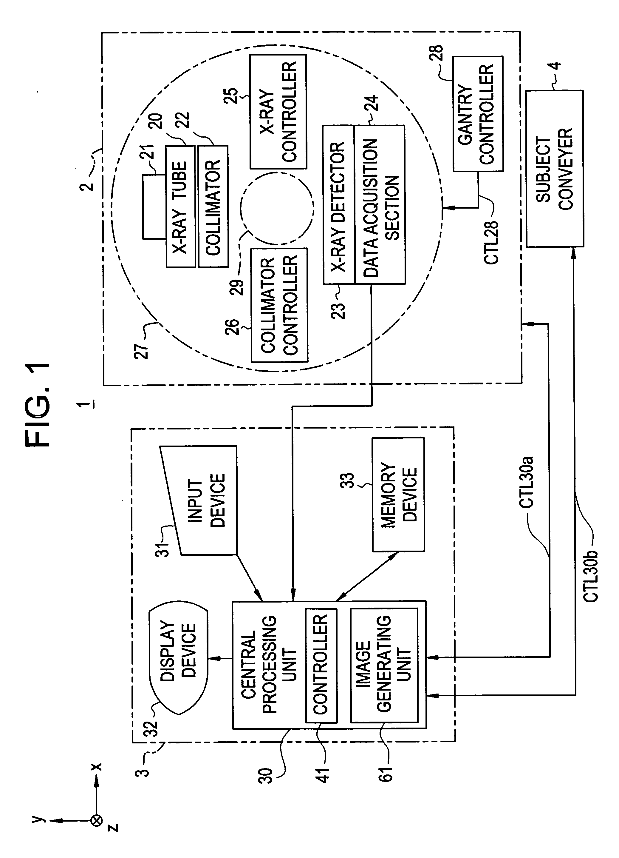
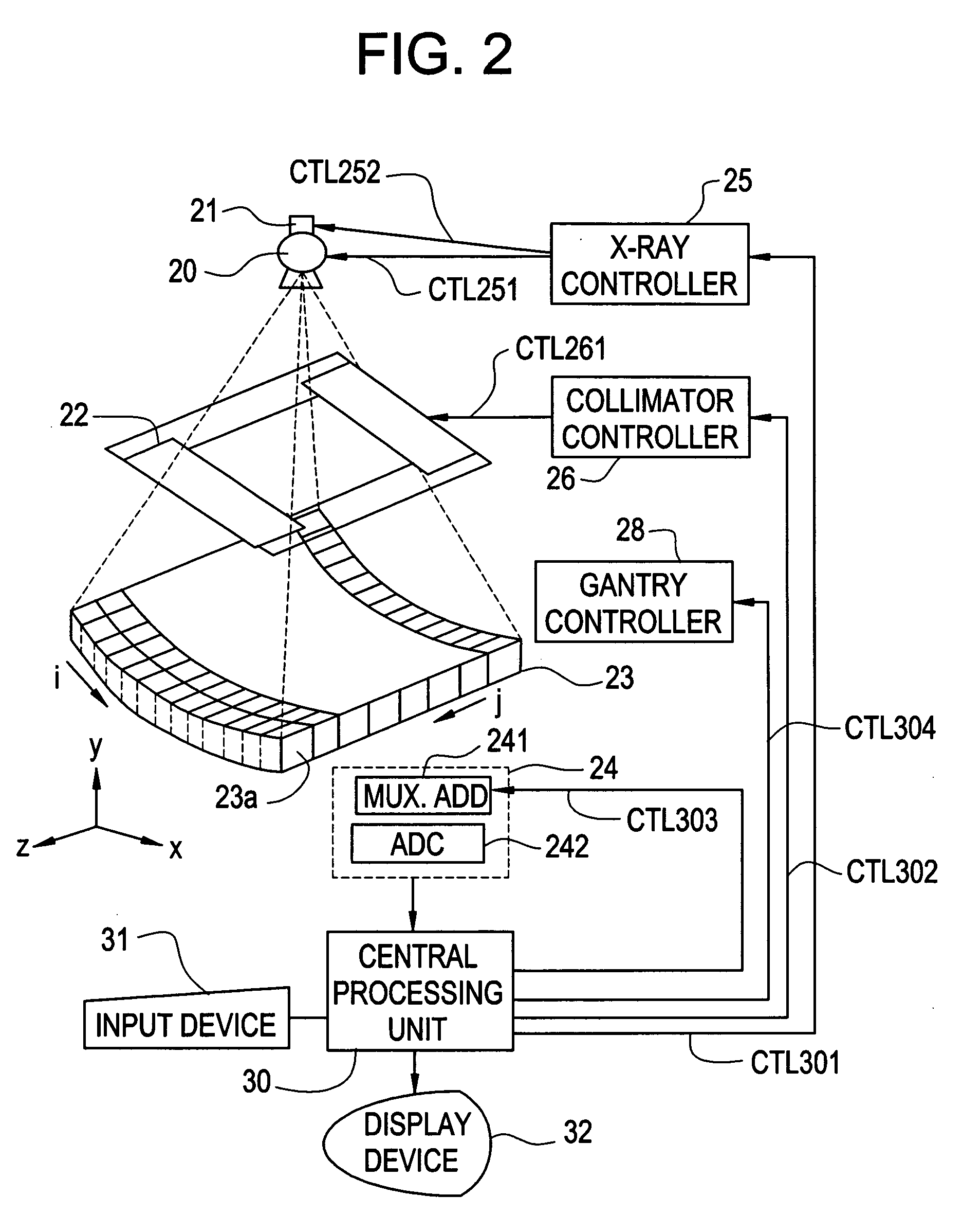
[0026]FIG. 1 is a block diagram showing an overall construction of an X-ray CT apparatus 1 used as an imaging apparatus illustrative of a first embodiment according to the present invention, and FIG. 2 is a configuration diagram showing an essential part of the X-ray CT apparatus 1 of the embodiment according to the present invention, respectively.

[0027] As shown in FIG. 1, the X-ray CT apparatus 1 includes a scanning gantry 2, an operation console 3 and a subject moving device or moving section 4.

[0028] The scanning gantry 2 has an X-ray tube 20, an X-ray tube moving section 21, a collimator 22, an X-ray detector 23, a data acquisition section 24, an X-ray controller 25, a collimator controller 26, a rotational section 27 and a gantry controller 28. The scanning gantry 2 scans a subject supported by a table section 101 moved to an imaging space 29 by a table moving section 102 of the subject moving device 4 to be described later to thereby obtain projection data of the subject as...

second embodiment

[0090]FIG. 9 is a block diagram showing the construction of an essential part of an X-ray CT apparatus illustrative of a second embodiment according to the present invention.

[0091] As shown in FIG. 9, the present embodiment is similar to the first embodiment except that it has an error calculation unit 401 and an error memory unit 402, and the function of the pressure control unit 205 differs. Therefore, dual components are given the same reference numerals and their explanations are therefore omitted. Incidentally, the error calculation unit 401 employed in the present embodiment corresponds to an error calculator of the present invention. The error memory unit 402 employed in the present embodiment corresponds to an error memory of the present invention. The pressure control unit 205 of the present embodiment corresponds to a pressure controller of the present invention.

[0092] The respective portions different from the first embodiment will be explained below.

[0093] The error c...

third embodiment

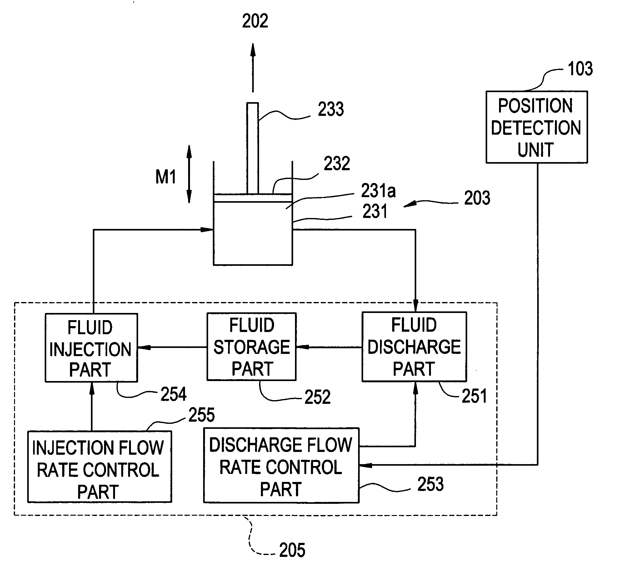
[0101]FIG. 11 is a block diagram showing the construction of a subject moving device 4 in an X-ray CT apparatus of a third embodiment according to the present invention.

[0102] As shown in FIG. 11, the present embodiment is similar to the first embodiment except that a position detection unit 103 of the subject moving device 4 differs. Therefore, dual components are given the same reference numerals and their explanations are omitted.

[0103] As shown in FIG. 11, the position detection unit 103 of the present embodiment is provided at a sixth shaft 204b of a second support bar 204 and includes an angle measuring instrument for measuring a tilt angle θ at which the second support bar 204 is inclined with respect to the horizontal direction. The angle measuring instrument of the position detection unit 103 measures a tilt angle using, for example, a rotary encoder. Here, the second support bar 204 is rotated with a rise in the table section with a table section 101 extending in the hor...


PUM


Abstract

With the object of, when a table unit is moved downward as viewed in a vertical direction by use of an actuator, smoothly moving the table unit and enhancing operability, when the actuator moves the table unit from a first position in the vertical direction to a downward second position, a pressure controller adjusts the amount of fluid held in the actuator on the basis of the first position of the table unit, detected by a position detector to thereby control pressure based on the fluid.

Description

BACKGROUND OF THE INVENTION [0001] The present invention relates to an imaging apparatus and a subject moving device thereof, and particularly to an imaging apparatus for imaging an image of a subject moved to an imaging space, and a subject moving device thereof. [0002] In an imaging apparatus such as an X-ray CT (Computed Tomography) apparatus or the like, a subject moving device moves a subject to an imaging space, and a scanning gantry scans the subject moved to the imaging space to obtain row data of the subject. An image about a tomographic plane of the subject is generated by reconstruction on the basis of the obtained row data. Such an X-ray CT apparatus has been utilized for a wide range of uses such as a medical use, an industrial use, etc. [0003] The scanning gantry in the X-ray CT apparatus includes an X-ray tube and an X-ray detector. The X-ray tube applies X rays to the subject and the X-ray detector detects the X rays transmitted through the subject to generate projec...

Claims


Application Information

Patent Timeline
IPC IPC(8): A61B6/04
CPCA61B6/032A61B6/0457A61B6/0487
Inventor ARIYAMA, NAOKIFUJIMOTO, RYOSUKEIZUHARA, AKIRA
Owner GE MEDICAL SYST GLOBAL TECH CO LLC
Why Eureka
Try Eureka