
Dynamic warp map generation system and method

a dynamic warp map and map generation technology, applied in the field of electronic image warping, can solve the problems of limiting the complexity and flexibility of spatial transformation, affecting the accuracy of spatial transformation,

Active Publication Date: 2006-06-08
GEO SEMICONDUCTOR INC
View PDF19 Cites 29 Cited by
  • Summary
  • Abstract
  • Description
  • Claims
  • Application Information

AI Technical Summary

Problems solved by technology

In display systems, in such transformations, the image data suffer intrinsic and situational distortions.
On the other hand, situational distortions depend on particular circumstances.
This objective often restricts the complexity and flexibility of the spatial transformation.
Both approaches are restrictive as not all warps can be separated into 1D warps and a pixel-by-pixel description is not suited for varying distortions, in addition to being very expensive to implement.
Obviously this method is not efficient, and in the case of real time video applications, it is not practical.
This technique requires substantial memory to store all the warp maps.
Accordingly, this method becomes impractical in the case of too many parameters and configurations.
Furthermore, the choice of a warp map is limited to a given set of pre-determined distortion parameters, which could greatly compromise the quality of the output image.

Method used


Image

  • Dynamic warp map generation system and method
  • Dynamic warp map generation system and method
  • Dynamic warp map generation system and method

Examples


Embodiment Construction

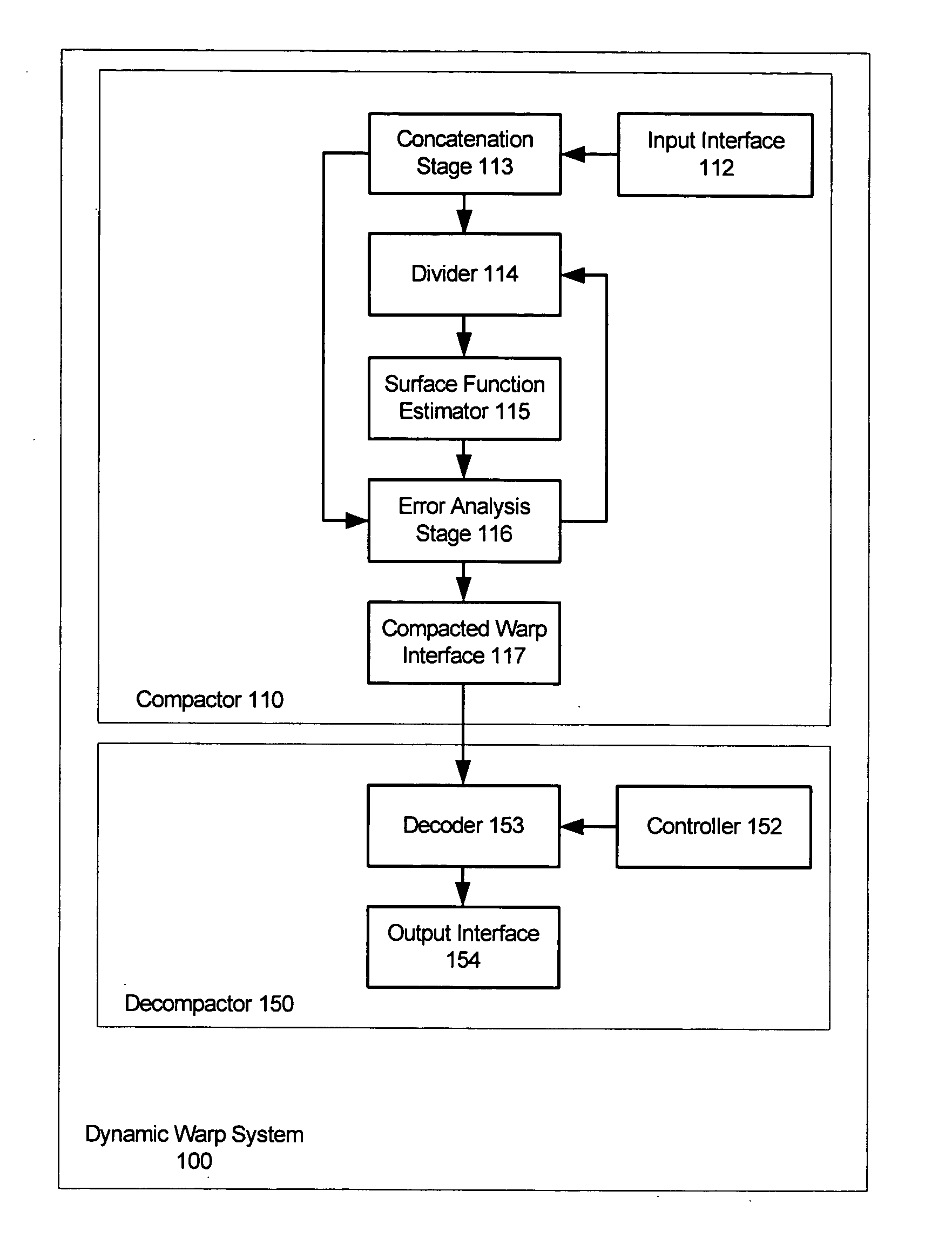
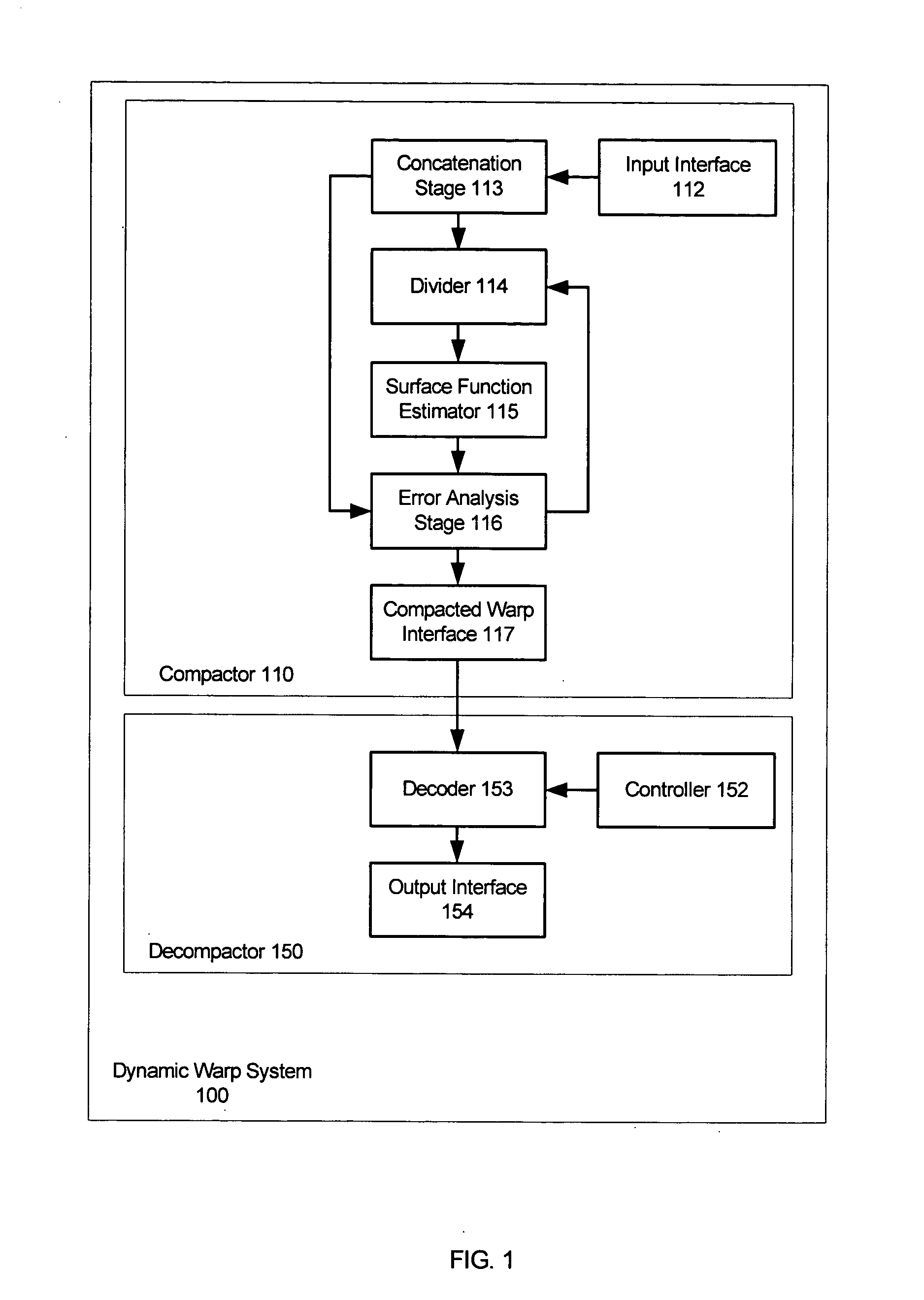
[0054] Reference is first made to FIG. 1 that illustrates an example of a dynamic warp system 100 made in accordance with the present invention. Dynamic warp system 100 comprises compactor 110 and decompactor 150. Compactor 110 comprises input interface 112, concatenation stage 113, divider 114, surface function estimator 115, error analysis stage 116, and compacted warp interface 117. Decompactor 150 comprises controller 152, decoder 153, and output interface 154.

[0055] In any display system there are optical and geometric distortions associated with a set of distortion parameters. Some of these parameters represent the geometric transformation specific to a display system. For instance, the shape and size of the display surface in a projection system are important geometric parameters. A curved display surface, for example, has a specific surface maps with associated parameters. Other geometric parameters may define situational distortions. For example, the horizontal and vertica...


PUM


Abstract

Dynamic warp map generation system and corresponding method are disclosed. A compactor obtains spatial transformation parameters along with geometric and optical distortion parameters and combines them to form hybrid grid data in a hybrid vector space. This vector space is divided into hybrid blocks. In each hybrid block, the grid dataset is fitted with a hypersurface and the surface coefficients are saved in an interface. A decompactor obtains dynamic control parameters representing varying distortion parameters and generates a hybrid space vector. According to the hybrid space vector, a warp map is decoded from the hypersurface coefficients that compensates for dynamic geometric and optical distortions. In another example of the present invention, the dynamic warp map generation system is used for color gamut transformation.

Description

FIELD OF THE INVENTION [0001] This invention relates to electronic image warping, and more particularly to dynamic warp map generation in the case of varying distortions. BACKGROUND OF THE INVENTION [0002] Two-dimensional digital image processing comprises transforming the digital content of an input image and producing output digital image data to produce an output image. In display systems, in such transformations, the image data suffer intrinsic and situational distortions. Intrinsic distortions are those characteristics of the display system that do not change under different circumstances. Examples of these distortions are tangential and radial lens distortions, the most common case of which are pincushion and barrel distortions. [0003] On the other hand, situational distortions depend on particular circumstances. Common examples of these distortions are horizontal and vertical keystone distortions. Some distortions could be considered intrinsic or situational depending on the ...

Claims


Application Information

Patent Timeline
Patent Type & Authority Applications(United States)
IPC IPC(8): G06K9/36
CPCG06T3/0093G06T3/18
Inventor BASSI, ZORAWAR S.LEE, LOUIESMITH, GREGORY LIONEL
Owner GEO SEMICONDUCTOR INC
Learn More