Cartridge, and toner container

a toner container and cartridge technology, applied in the field of toner containers and cartridges, can solve the problems of poor effect of enhancing the rigidity of the cleaning frame member, low rigidity of the periphery, and limited joint position in relation to space, and achieve the effect of wide joint surfaces

Inactive Publication Date: 2006-06-08
CANON KK
View PDF18 Cites 10 Cited by
  • Summary
  • Abstract
  • Description
  • Claims
  • Application Information

AI Technical Summary

Benefits of technology

[0017] An object of the present invention is to provide a cartridge and a toner container which are almost free of deformation at the peripheries of joints and have secured wide joint surfaces.
[0018] Another object of the present invention is to provide a cartridge and a toner container which have a high positioning precision for component parts and have a high rigidity.
[0019] Still another object of the present invention is to provide a cartridge and a toner container which are recyclable with ease.
[0020] A further object of the present invention is to provide a cartridge and a toner container which have employed a novel joining technique that enables utilization of a simple joining assembly.

Problems solved by technology

However, such conventional joining techniques have had the following problems.
As the result, there arises a problem that its periphery has a low rigidity.
Hence, the effect of enhancing the rigidity of the cleaning frame member may become poor also after the drum bearing 138 has been joined thereto.
Moreover, in joining with screws, the joint position is limited in relation to space.
In addition, since the joint area is also small as stated above, the positioning precision of the drum unit D tends to be low.
There also have been such problems.
However, where it is attempted to make the drum bearing and the cleaning frame member integrated by joining them both widely and around the shaft of the photosensitive drum in an annular shape (or arc shape) according to the conventional methods, e.g., by the resin joining (by injection of molten resin) or by injecting a hot melt, an adhesive or the like, there has been a problem that the peripheries of joints tend to deform under heat and pressure because, in injecting the molten resin or in injecting the hot melt, the joints must be heated to a high temperature at the time of injection in order to melt the material to be injected, or a high pressure is required in order to inject a highly viscous material.
A case in which the frame members (and component parts) are joined using a material different from materials for them, such as hot melts, adhesives or the like, is undesirable because such a case is disadvantageous in regard to the recycling of materials after cartridges having been used are collected and there is a possibility of causing a lowering of quality such as a lowering of mechanical physical properties and flame retardance of recycled materials (regenerated materials).

Method used


Image

  • Cartridge, and toner container
  • Cartridge, and toner container
  • Cartridge, and toner container

Examples


embodiment 1

[0063] (Joining of Cleaning Frame Member and Drum Bearing; Embodiment 1)

[0064]FIG. 4 is a perspective view showing in detail the relationship of attachment between the drum bearing 38 (first component part), which supports the photosensitive drum, and the cleaning frame member 13 (second component part). The attaching of the drum bearing 38 to the cleaning frame member 13 and the attaching of a unitized photosensitive drum unit D to the cleaning frame member 13 are specifically described below.

[0065] The drum bearing 38 is, as shown in FIGS. 4 and 5, integrally provided with a large-diameter protrusion 38a and a small-diameter protrusion 38b. This small-diameter protrusion 38b is connected with an end of a disk portion 38c at the middle of the large-diameter protrusion 38a in its axial direction (lengthwise direction). The cleaning frame member 13 is, as shown in FIG. 4, provided on a sidewall 13b thereof with a bearing attaching hole 13h into which an outer peripheral portion 38b2...

embodiment 2

[0098] (Joining of Toner Frame Member and Side Cover; Embodiment 2)

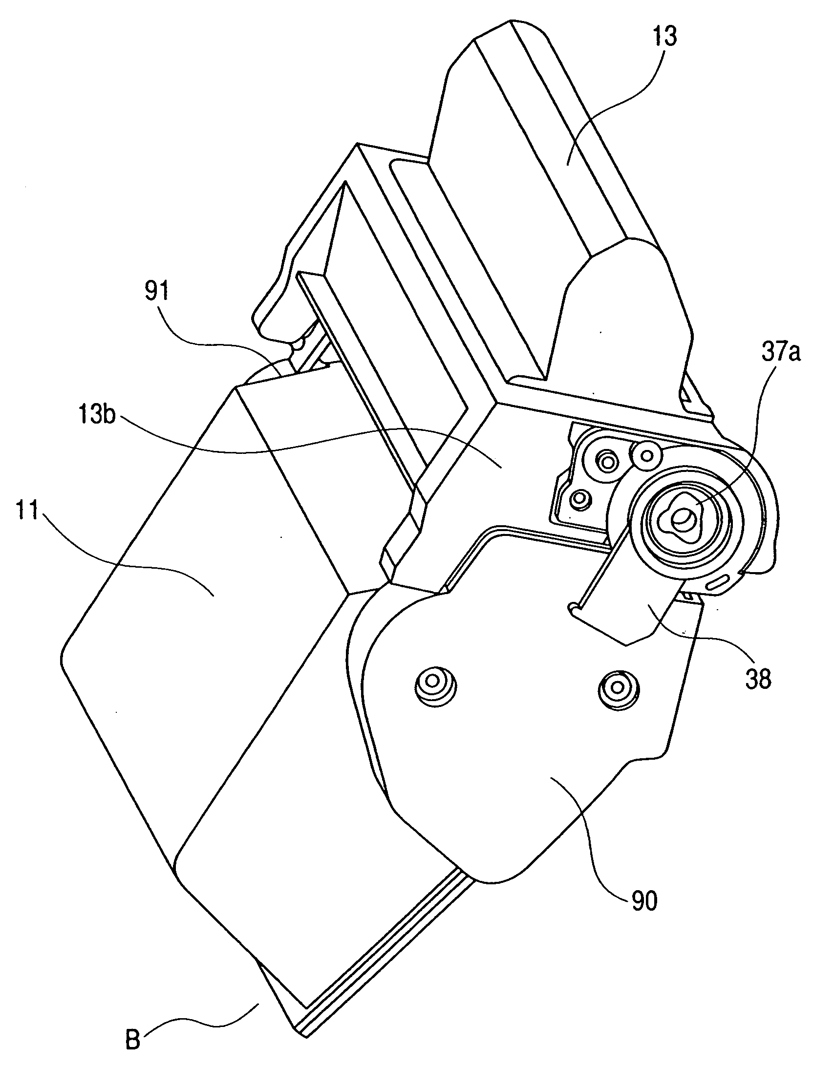
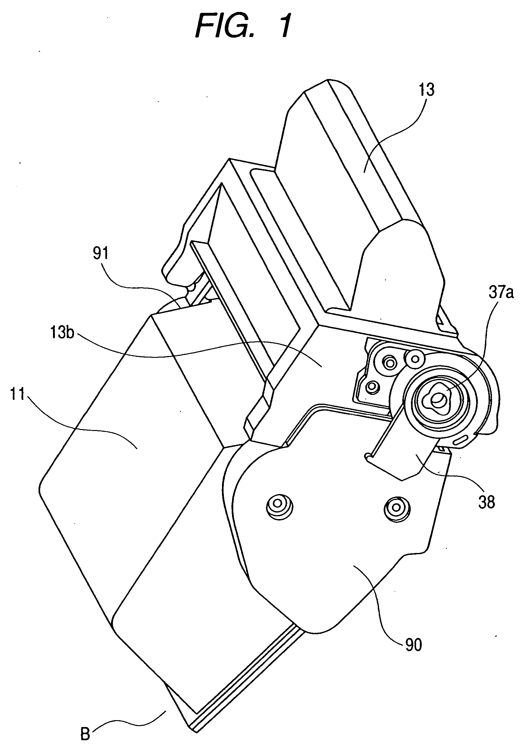
[0099] The joining of the toner frame member 11 and side covers 90 and 91 is described below (see FIGS. 1 and 12 to 14).

[0100] The toner frame member 11 described previously is provided with protrusions 50 and 51 for its positioning to the side cover 90(91: the side cover on the opposite side). Recesses 52 and 53 are also provided on the side cover 90(91) side correspondingly to the protrusions 50 and 51. As shown in FIG. 14, the protrusion 50 is fitted to the recess 52, where they serve as the center of rotation in the direction of an arrow g shown in FIG. 12, and the protrusion 51 is fitted to the recess 53, where they determine the rotational direction (position) of the toner frame member and side cover 90(91). Also, the positioning in the lengthwise direction is determined by making end faces 50a and 51a of the protrusions 50 and 51 come to the ends of the recesses 52 and 53 at their bottom faces 52a and 53a, re...

embodiment 3

[0111] (Joining of Toner Container Component Parts; Embodiment 3)

[0112] In the toner container having at least a first component part formed of a first styrene resin composition and a second component part formed of a second styrene resin composition, the first component part and the second component part were joined with the terpene type solvent (d-limonene). As a result, joining in a high positioning precision was achieved, and a toner container was obtained which was almost free of deformation at the periphery of the joint and had a high rigidity.

[0113] Incidentally, the terpene type solvent was fed by utilizing the capillarity. Also, HIPS (a styrene polymer mixed with 8% by weight of polybutadiene rubber having an average particle diameter of 0.8 μm) was used as materials for the respective component parts.


PUM

PropertyMeasurementUnit
average particle diameteraaaaaaaaaa
sectional areaaaaaaaaaaa
depthaaaaaaaaaa

Abstract

A first component part formed of a first styrene resin composition and a second component part formed of a second styrene resin composition are fastened by solvent welding by means of a terpene type solvent, to provide a cartridge which is almost free of deformation at the peripheries of joints, has a high positioning precision for component parts and has a high rigidity.

Description

CROSS-REFERENCE TO RELATED APPLICATION [0001] This application is a divisional of application Ser. No. 10 / 866,115, filed Jun. 14, 2004, pending.BACKGROUND OF THE INVENTION [0002] 1. Field of the Invention [0003] This invention relates to a cartridge detachably mountable to an electrophotographic image forming apparatus employing electrophotography, such as a laser beam printer or a copying machine. Here, the electrophotographic image forming apparatus is one that forms images on a recording medium by using an electrophotographic image forming system. Then, as examples of the electrophotographic image forming apparatus, it includes, e.g., electrophotographic copying machines, electrophotographic printers (e.g., laser beam printers and LED printers), facsimile machines, and word processors. Incidentally, a process cartridge is one in which a charging means, a developing means or a cleaning means and an electrophotographic photosensitive member are integrally joined in a cartridge and ...

Claims


Application Information

Patent Timeline
Patent Type & Authority Applications(United States)
IPC IPC(8): G03G21/16G03G15/06G03G15/00G03G15/08
CPCB29C65/548G03G15/757B29C65/542B29C66/5344B29C65/4815B29C65/4895Y10S222/01B29C66/112B29C66/114B29C66/1222B29C66/1224B29C66/71B29C66/73161B29C66/73921B29K2995/0072G03G15/00G03G21/1619B29K2025/06B29K2023/16B29K2009/06B29K2009/00B29K2007/00G03G15/06G03G15/08
Inventor SUZUKI, AKIRAANAN, OSAMU
Owner CANON KK
Why Eureka
Try Eureka