
Removable resectoscope provided with an external shaft

a resectoscope and external shaft technology, applied in the field of resectoscopes provided with external shafts, can solve the problems of limiting the available shaft length and the available shaft length that can be inserted into the typical human body, and achieve the effect of simple design and greater available shaft length

Inactive Publication Date: 2006-06-08
OLYMPUS WINTER & IBE
View PDF14 Cites 19 Cited by
  • Summary
  • Abstract
  • Description
  • Claims
  • Application Information

AI Technical Summary

Benefits of technology

[0005] The objective of the present invention is to create a resectoscope of simple design offering greater available shaft length.
[0007] The inner shaft may be affixed to the resectoscope main body, preferably in a permanent manner. This very simple design entirely circumvents the known inner connector element.
[0009] Illustratively, the inner shaft may be of constant cross-sectional shape and smooth as far as its proximal end by which it may be inserted into a resectoscope main body borehole where it might be permanently soldered or welded into place. The inner shaft also may be connected by means of a thread or a bayonet lock to the borehole, or it may be merely plugged into the borehole and remain therein in a frictional or press-fit manner. Such a design is radially compact and consequently the enclosing outer connector also may be made compact and the entire assembly slender.
[0012] Thereby, the inner shaft is fitted with a connector element that, upon closure of the outer connector element, shall engage between the outer shaft and the resectoscope main body and in this way can be clamped into place when the outer connector element is closed. This feature offers a simple design variant where, however, the inner shaft can be removed only in the proximal direction from the outer shaft after the outer shaft has been detached from the main body—whereas, in other designs, the inner shaft may be removed in the distal direction from the outer shaft after loosening the inner connector element.

Problems solved by technology

One of the main problems encountered in resectoscopes is the available length of the shaft that can be inserted into the typical human body.
Accordingly, designers in this field attempt foremost to maximize the shaft length while reducing resectoscope length elsewhere, but difficulties arise.
The design of known resectoscopes comprising two externally actuated connector elements, inherently limits the available shaft length.

Method used


Image

  • Removable resectoscope provided with an external shaft
  • Removable resectoscope provided with an external shaft
  • Removable resectoscope provided with an external shaft

Examples


Embodiment Construction

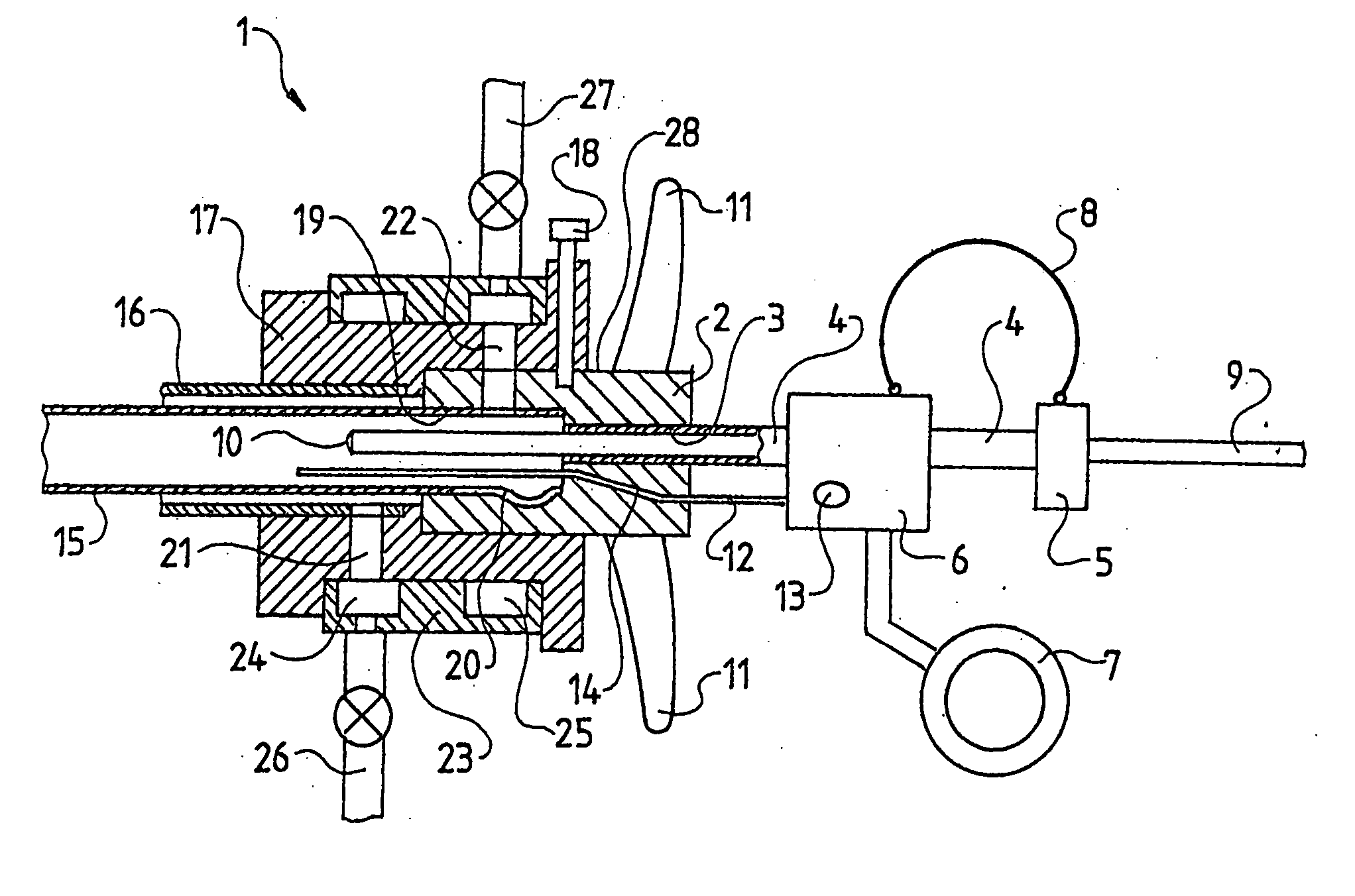
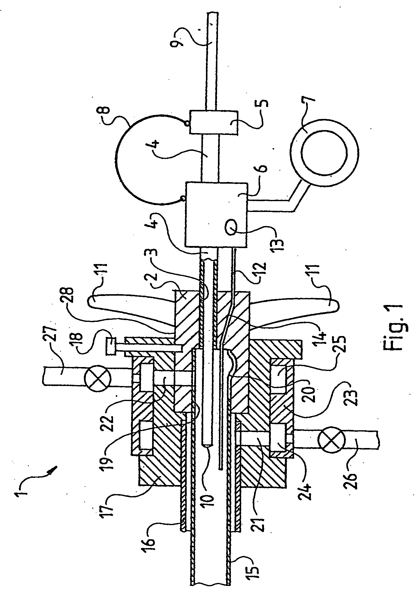
[0015]FIG. 1 is a section of a first embodiment of a resectoscope of the invention, and

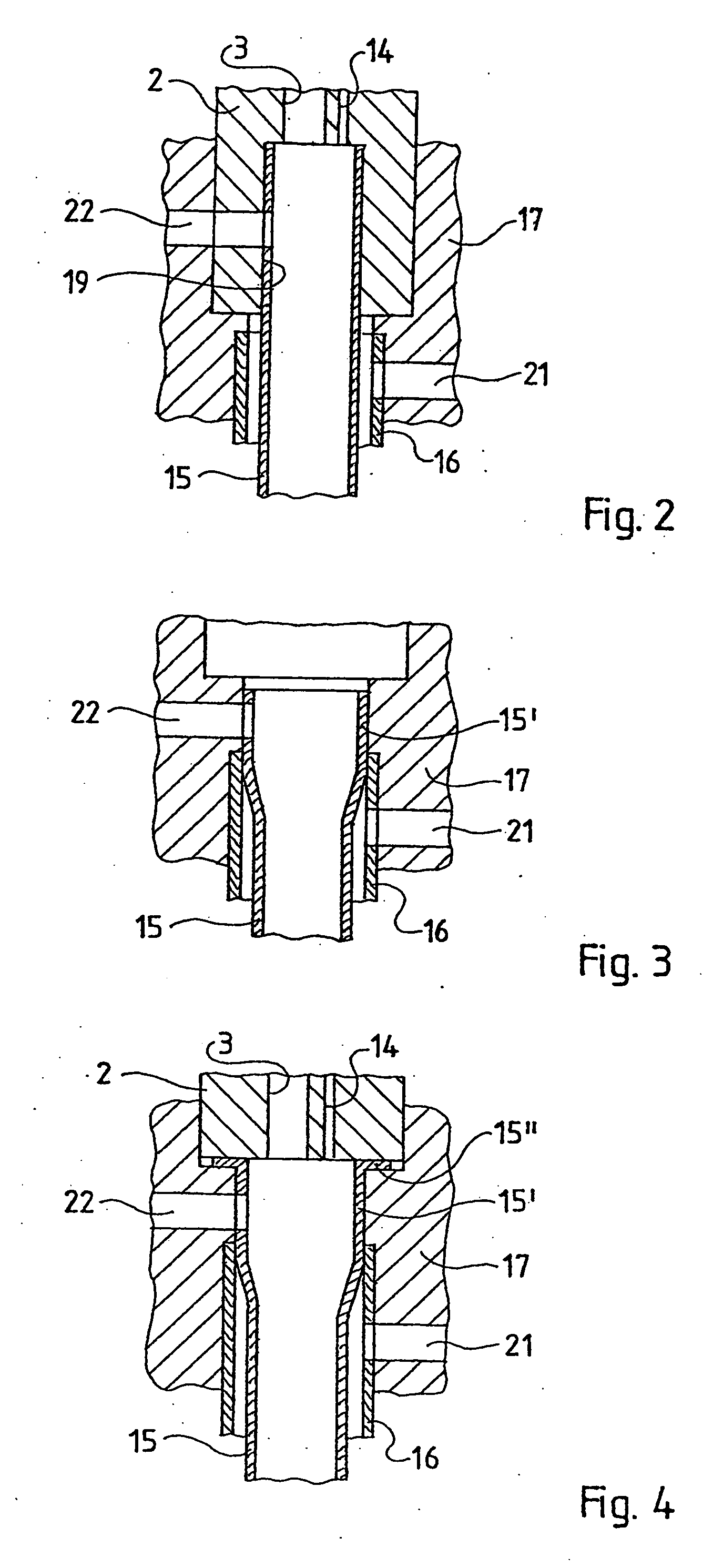
[0016]FIGS. 2-4 show three further embodiments of details of FIG. 1.

DETAILED DESCRIPTION OF THE INVENTION

[0017] The resectoscope 1 shown in FIG. 1 comprises a main body 2 to which an optics guide tube 4 is affixed inside a borehole 3, the tube 4 passing proximally a distance from the main body 2 through an optics guide plate 5 within which it is affixed.

[0018] A carriage 6 with a thumb ring 7 runs on the optics guide tube 4 and is connected by means of a leaf spring 8 with the optics guide tube 5. As shown by FIG. 1, an optics 9 having an objective 10 can be inserted by means of the optics guide tube 4 in the distal direction, far beyond the main body 2.

[0019] By holding the implement in one hand, the surgeon may actuate finger grips 11 at the main body 2 to displace the carriage 6 in the axial direction of the resectoscope 1 to move an elongated support 12 affixed to the carriage 6, indicated...


PUM


Abstract

A urological resectoscope (1) including a main body (2) that is traversed by an optics (9) and to which the guide (4) of a carriage (6) is affixed proximally and to which are mounted an inner shaft (15) and an outer shaft (16). The inner and outer shaft both extend distally from the main body. The outer shaft (16) encloses the inner shaft (15) and is detachable from the main body via an externally actuated outer connector element (17). The outer connector element (17) is connected to the main body (2).

Description

BACKGROUND OF THE INVENTION [0001] For decades already resectoscopes have been the backbone of urological instrumentation. For permanent rinsing they comprise an inner and an outer shaft, rinsing fluid being fed from the inner shaft and then being evacuated through the annular space between said shafts. The outer shaft is detachable by means of an externally actuated connector element. The optics monitoring the surgery zone, and the implement operational therein, for instance the conventional high-frequency (hf) cutting loop, run through the inner shaft. [0002] Regarding known resectoscopes of the species described in U.S. Pat. Nos. 5,807,240 and 5,486,155, the inner shaft also is detachable by means of an externally actuated connector element. The connector elements for the outer and inner shafts hereafter are called external connector element and inner connector element, respectively. In known resectoscopes, the inner connector element also is actuated externally and it directly e...

Claims


Application Information

Patent Timeline
Patent Type & Authority Applications(United States)
IPC IPC(8): A61B1/00A61B17/32A61B1/12A61B18/14
CPCA61B1/00135A61B1/12A61B18/149A61B1/018A61B1/307A61B17/320016A61B18/1492
Inventor AUE, THOMAS
Owner OLYMPUS WINTER & IBE
Learn More