Surgical instrument

a surgical instrument and guide technology, applied in the field of surgical instruments, can solve the problems of difficult implementation of procedures, difficult to precisely position the guide, and often inability to finely adjust the guide position, so as to achieve accurate positioning of the guide and less invasive

Inactive Publication Date: 2006-06-08
BIOMET MFG CORP
View PDF7 Cites 94 Cited by
  • Summary
  • Abstract
  • Description
  • Claims
  • Application Information

AI Technical Summary

Benefits of technology

[0008] It is an advantage of the invention that the surgical instrument provided is adapted to be attached to the bone within the space of a small incision, and by attaching the first marker to the base member and the second marker to the guide, it is not necessary to make any further incisions around the operating area in order to attach a fixed marker to a bone. This results in operations being less invasive than previously.
[0009] Preferably, the guide is provided with a guide surface for guiding a surgical tool.
[0010] Preferably, the instrument further comprises an adjustment means disposed between the base member and the guide to permit relative motion in three dimensions between the base member and the guide.
[0011] It is a further advantage of the invention that a surgeon is able to accurately position the guide, by virtue of its capability to be adjusted in three dimensions relative to the base member.
[0012] Preferably, the instrument also comprises a locking mechanism, suitable for locking the guide in a fixed position relative to the base member. The locking mechanism may comprise a single locking means, first and second locking means or first, second and third locking means.
[0013] Preferably, the adjustment means comprises a stem, having first and second ends. The first end of the stem may be slidably received within a recess extending through the base member. Preferably, the sliding connection is such that the distance of the second end of the stem from an adjacent surface of the base member may be adjusted.

Problems solved by technology

However, the procedures can be difficult to implement.
Although the required position of the guide relative to the bone is indicated on the screen, in practice, it is extremely difficult to attach the guide in precisely the right position.
Once the holes are drilled, further, fine adjustment of the position of the guide is often not possible.
Exact matching of the position and orientation of the guide with the ideal position indicated on the screen is therefore extremely difficult.
A further disadvantage of the procedure is the need for at least one extra incision in the leg, spaced from the operative incision, in order to attach a fixed marker to a bone.
The provision of the fixed marker also results in additional bone damage, caused by the screws that hold the marker in place.

Method used


Image

  • Surgical instrument
  • Surgical instrument
  • Surgical instrument

Examples


second embodiment

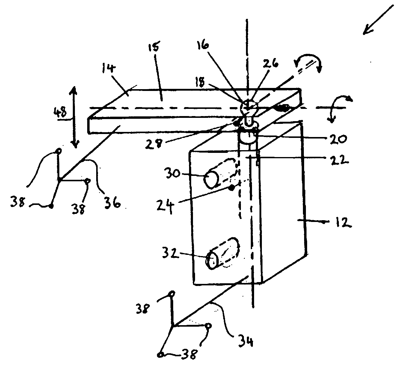
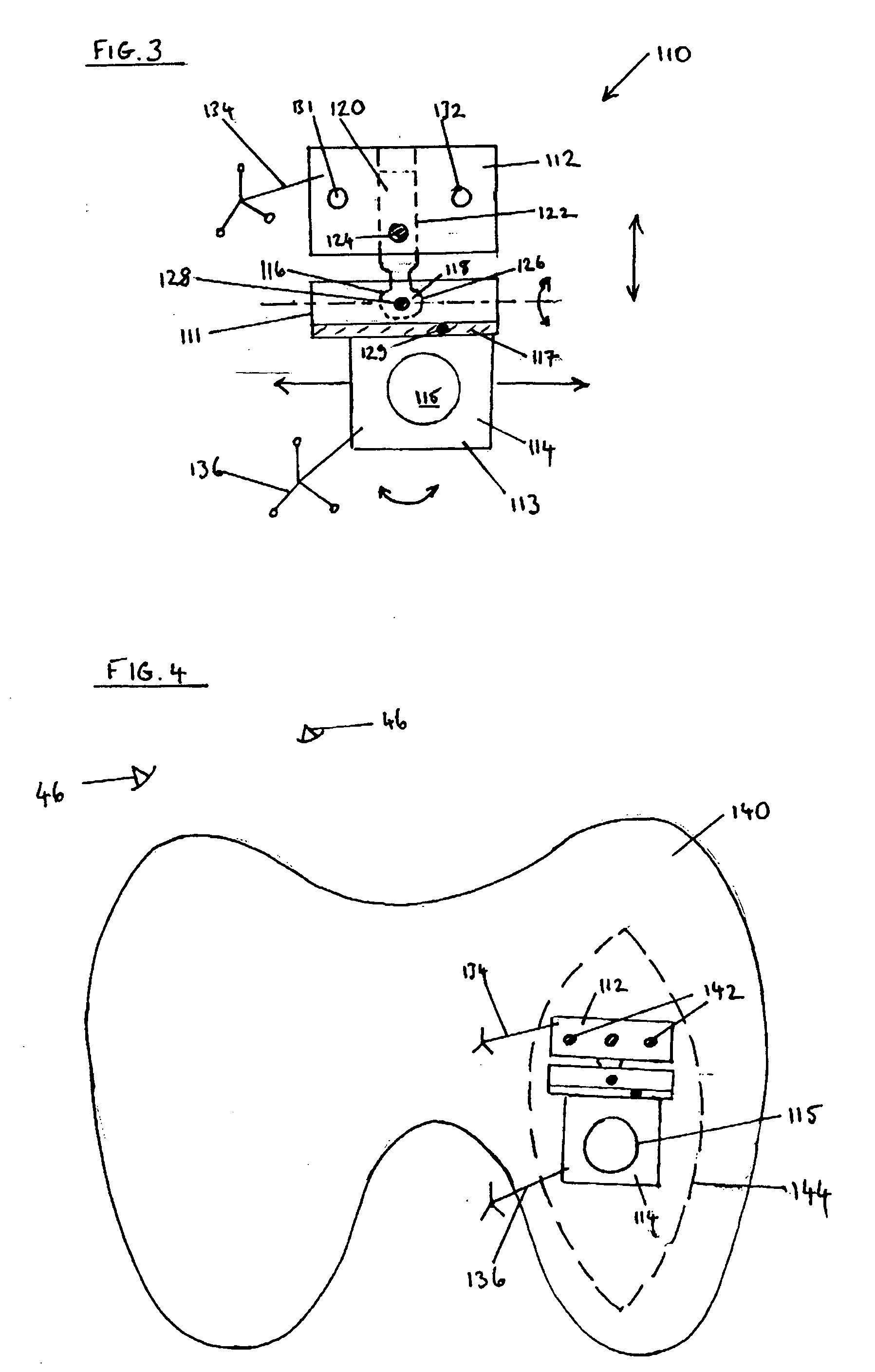
[0046] Referring now to FIG. 3, a surgical instrument is indicated generally at 110. The surgical instrument 110 comprises a base member 112 and a cutting guide 114, adjustably connected together by means of a ball and socket joint 116. The cutting guide 114 is provided in first and second parts 111,113. A circular hole 115 is provided through second part 113 of the cutting guide 114, which, in use, guides a drill, brooch or other cutting implement. A ball 118 of the joint 116 is mounted at the end of a stem 120, which is slidably received in an aperture 122 in the base member 112. A locking means 124, for example, a locking screw, is provided in the base member 112 for locking the position of the ball 118 and stem 120 relative to the base member 112.

[0047] The ball 118 is received in a socket 126 provided in the first part 111 of the cutting guide 14. A second locking means 128 is provided on the first part of the cutting guide 114, which locks the cutting guide relative to the bal...

first embodiment

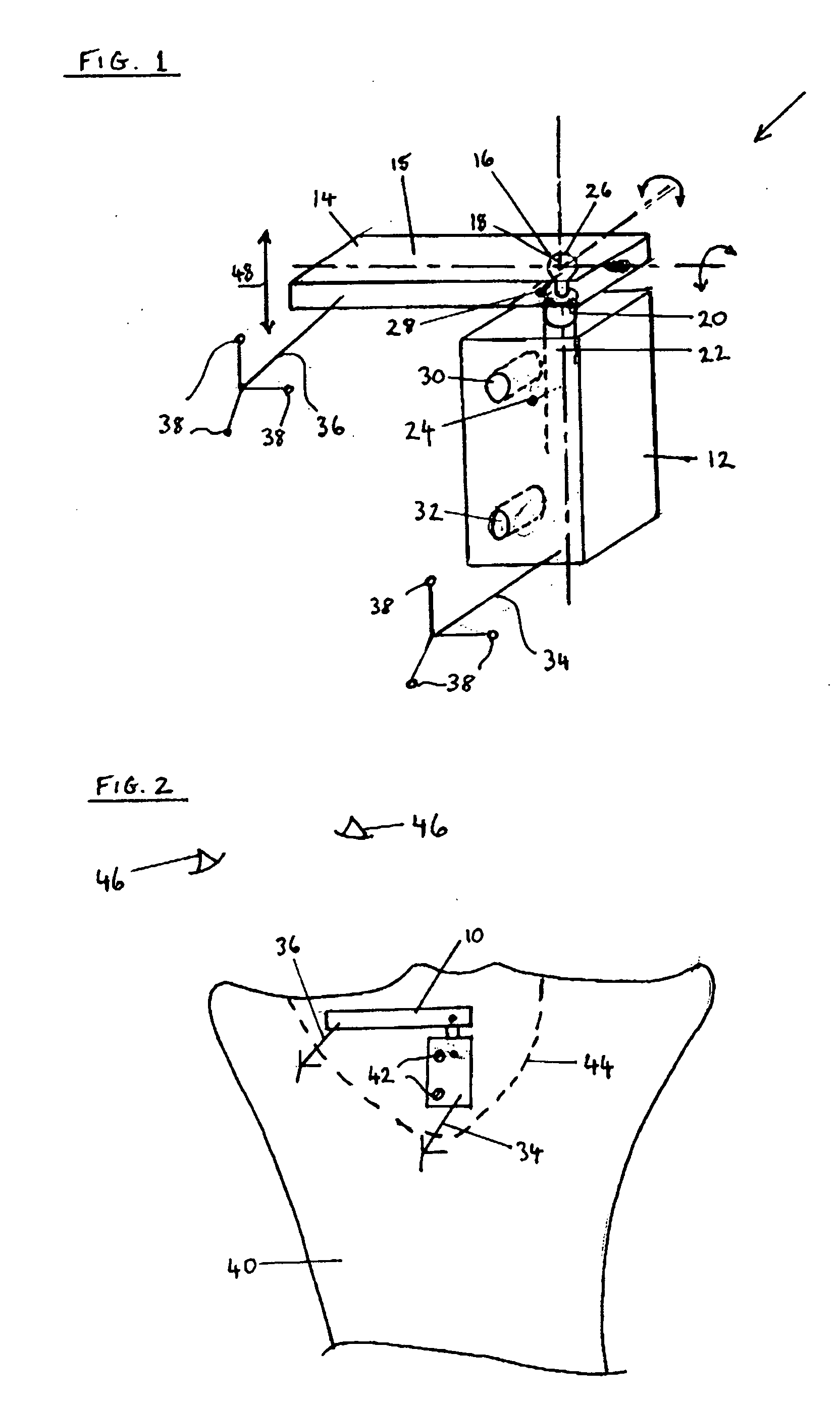
[0048] As in the first embodiment, first and second apertures 130, 132 are provided through the base member 112, through which screws may be driven in order to secure the surgical instrument to a bone. A first marker 134 is removably attached to the base member 112, and a second marker 136 is removably attached to the second part 113 of the cutting guide 114. The markers are those known in the art of digitised operative treatment as arrays as described previously.

[0049] The surgical instrument 110 is shown in use in FIG. 4 during a partial knee replacement operation. The instrument is attached to a femur 140, by means of a pair of screws 142, which pass through the apertures 131, 132. The instrument 110, without the markers 134, 136, is positioned against the femur 140 through an incision, indicated in dotted outline at 144. The operating arrangement is as described with regard to the first embodiment, with cameras 46 linked to a computer and computer screen (not shown) in a known c...


PUM


Abstract

A surgical instrument comprises a base member adapted to be attached to a bone, a guide adjustably connected to the base member, a first marker removably attached to the base member and a second marker removably attached to the guide. In navigated surgery, the first and second markers enable the position of the guide to be determined relative to the position of the base member and bone, to which it is attached. The guide may have a planar cutting surface for guiding a blade or a circular aperture for guiding a drill.

Description

RELATED APPLICATIONS [0001] This application claims priority to United Kingdom application serial number GB426767.0, filed Dec. 6, 2004. FIELD OF INVENTION [0002] This invention relates to a surgical instrument and particularly but not exclusively to an instrument for use in surgery employing surgical navigation. BACKGROUND [0003] During most types of orthopaedic surgery it is necessary to resect specific areas of bone. The precision of resection is particularly important during joint replacement surgery, where it is necessary to make a cut or drill a hole in a precise location and orientation relative to a patient's bone. Traditional methods use mechanical tools to reference off a remote area of bone in order to determine the correct position in which to cut or drill. However, recent advances have produced an alternative to physical referencing in the form of navigated surgery. [0004] In, for example, a knee replacement operation, a permanent marker, comprising an array of three re...

Claims


Application Information

Patent Timeline
Patent Type & Authority Applications(United States)
IPC IPC(8): A61B5/05A61B17/15A61B17/17A61B19/00
CPCA61B17/157A61B17/1764A61B19/5244A61B2019/5255A61B2019/5483A61B34/20A61B2034/2055A61B2090/3983
Inventor MURRAY, DAVID WYCLIFFEREEVES, EDWARD ALEXANDERTHOMAS, WILLIAM KEITH
Owner BIOMET MFG CORP
Why Eureka
Try Eureka