Apparatus and method for determining the relative position and orientation of neurostimulation leads

a technology of neurostimulation and apparatus, applied in the field of neurostimulation systems, can solve the problems of inability to obtain images, inability to accurately determine the relative position and orientation of neurostimulation leads, and inability to meet the needs of patients,

Active Publication Date: 2006-06-08
BOSTON SCI NEUROMODULATION CORP
View PDF37 Cites 103 Cited by
  • Summary
  • Abstract
  • Description
  • Claims
  • Application Information

AI Technical Summary

Problems solved by technology

Disadvantageously, X-ray and fluoroscopy require expensive equipment, significant time, and appropriate medical facilities, most of which are not readily available.
Disadvantageously, however, such images may not always be available.
Moreover, between the time of implant and follow-up visits, the leads may have shifted and the fluoroscope image may no longer be valid.
This can result in poor patient outcomes due to inappropriate or unexpected stimulation effects during fitting.

Method used


Image

  • Apparatus and method for determining the relative position and orientation of neurostimulation leads
  • Apparatus and method for determining the relative position and orientation of neurostimulation leads
  • Apparatus and method for determining the relative position and orientation of neurostimulation leads

Examples


Embodiment Construction

[0023] The following description is of the best mode presently contemplated for carrying out the invention. This description is not to be taken in a limiting sense, but is made merely for the purpose of describing the general principles of the invention. The scope of the invention should be determined with reference to the claim(s).

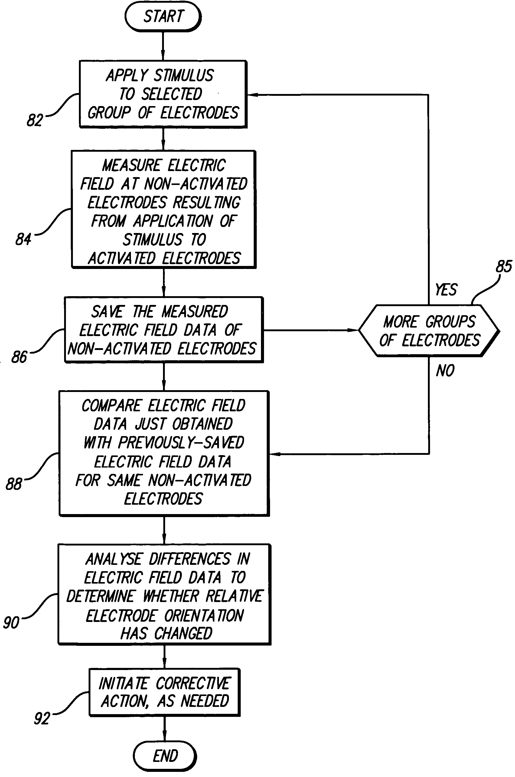
[0024] The present invention uses: (1) interelectrode impedance (one technique or embodiment) or (2) measured field potentials (another technique or embodiment) to determine the relative orientation of one electrode on an implanted lead to other electrodes on the implanted lead or adjacent implanted leads in the spinal column or other body / tissue location.

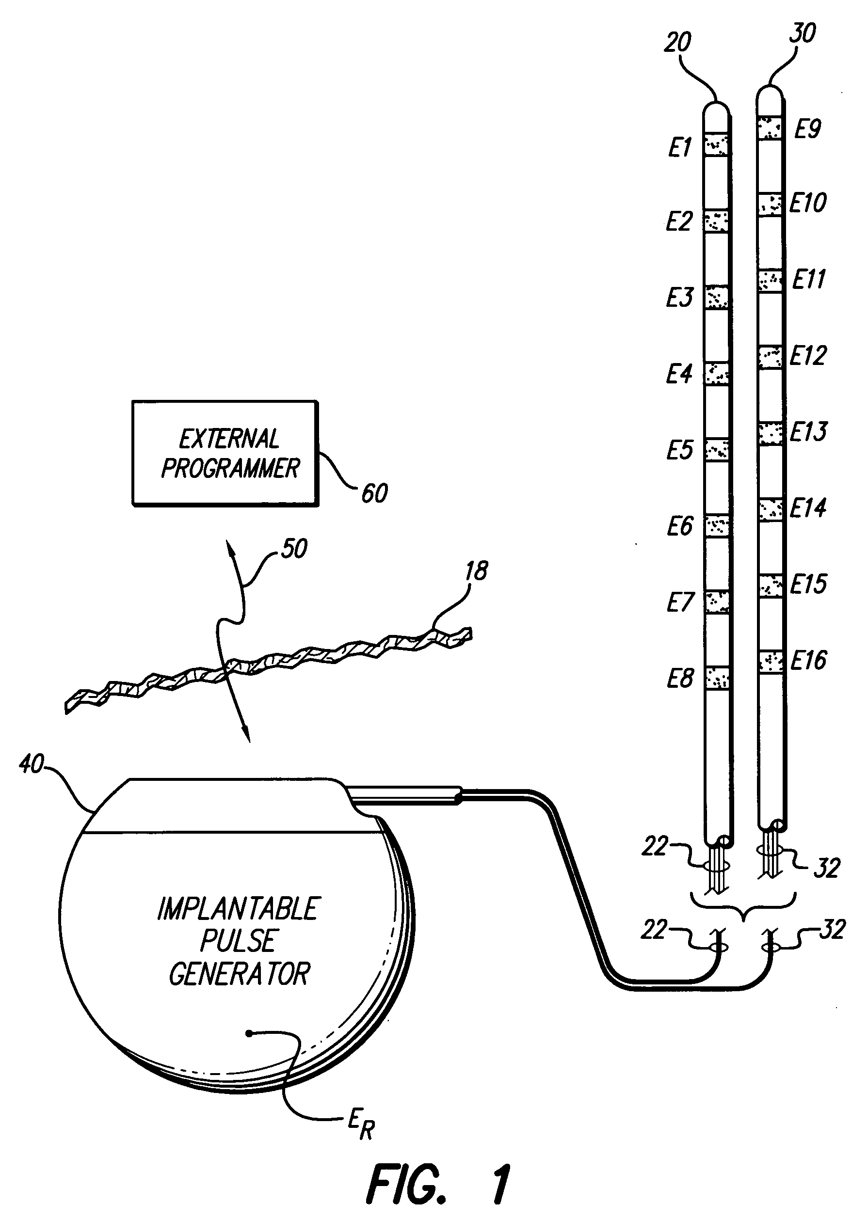
[0025] Before describing the two techniques, either of which may be used, it will be helpful to first briefly provide an overview of a representative neurostimulation system of the type with which the present invention may be used. A representative neurostimulation system is illustrated in FIG. 1. Such...


PUM


Abstract

Interelectrode impedance or electric field potential measurements are used to determine the relative orientation of one lead to other leads in the spinal column or other body / tissue location. Interelectrode impedance is determined by measuring impedance vectors. The value of the impedance vector is due primarily to the electrode-electrolyte interface, and the bulk impedance between the electrodes. The bulk impedance between the electrodes is, in turn, made up of (1) the impedance of the tissue adjacent to the electrodes, and (2) the impedance of the tissue between the electrodes. In one embodiment, the present invention makes both monopolar and bipolar impedance measurements, and then corrects the bipolar impedance measurements using the monopolar measurements to eliminate the effect of the impedance of the tissue adjacent the electrodes. The orientation and position of the leads may be inferred from the relative minima of the corrected bipolar impedance values. These corrected impedance values may also be mapped and stored to facilitate a comparison with subsequent corrected impedance measurement values. Such comparison allows a determination to be made as to whether the lead position and / or orientation has changed appreciably over time. In another embodiment, one or more electrodes are stimulated and the resulting electric field potential on the non-stimulated electrodes is measured. Such field potential measurements provide an indication of the relative orientation of the electrodes. Once known, the relative orientation may be used to track lead migration, to setup stimulation configurations and parameters for nominal stimulation and / or navigation. Also, such measurements allow automatic adjustment of stimulation energy to a previously-defined optimal potential field in the case of lead migration or postural changes.

Description

[0001] The present is a continuation of U.S. application Ser. No. 10 / 310,202, filed Dec. 3, 2002, to be issued on Jan. 31, 2006 as U.S. Pat. No. 6,993,384, which application claims the benefit of U.S. Provisional Patent Application Ser. No. 60 / 338,331, filed Dec. 4, 2001, each of which is incorporated herein by reference.BACKGROUND OF THE INVENTION [0002] The present invention relates to neurostimulation systems, such as a spinal cord stimulation (SCS) system, and more particularly to a method for determining the relative position and orientation of electrodes on a neurostimulation lead or leads used with such a system. [0003] In SCS systems, positioning of the leads is critical to the success of the therapy. During surgery, the physician places the leads in a very careful manner in order to locate the electrodes proximal to neural elements that are the target of the stimulation. During and after placement, stimulation energy is delivered to verify that the leads are indeed stimulat...

Claims


Application Information

Patent Timeline
Patent Type & Authority Applications(United States)
IPC IPC(8): A61N1/37A61N1/05A61N1/08
CPCA61B5/053A61N1/0551A61N1/08
Inventor BRADLEY, KERRYTHACKER, JAMES R.
Owner BOSTON SCI NEUROMODULATION CORP
Why Eureka
Try Eureka