
Directional input device and display orientation control

a directional input device and display orientation technology, applied in the field of computer processing and information manipulation, can solve the problems of unduly complicated known switch mechanisms, limited ability of directional input devices to work in both display orientations, and inability to provide users with quick results. , to achieve the effect of better integration of directional input devices

Active Publication Date: 2006-06-08
MICROSOFT TECH LICENSING LLC
View PDF11 Cites 41 Cited by
  • Summary
  • Abstract
  • Description
  • Claims
  • Application Information

AI Technical Summary

Benefits of technology

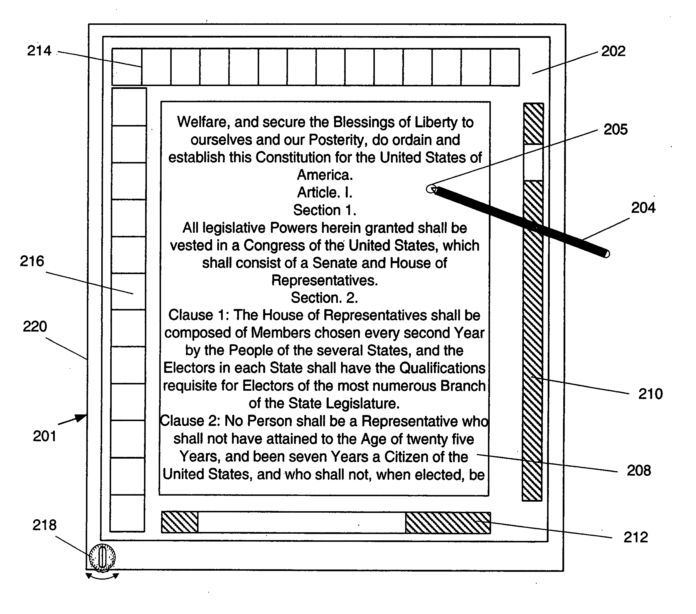
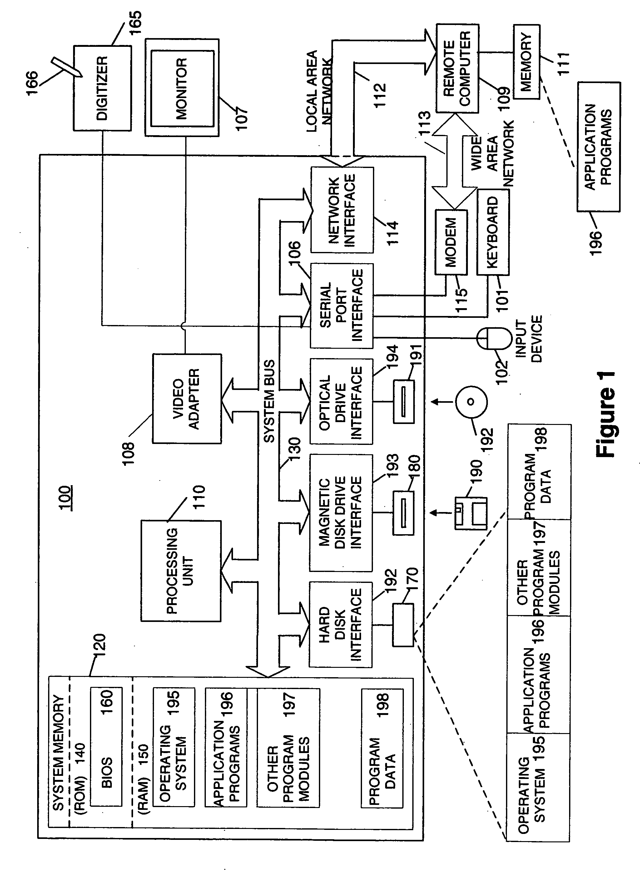
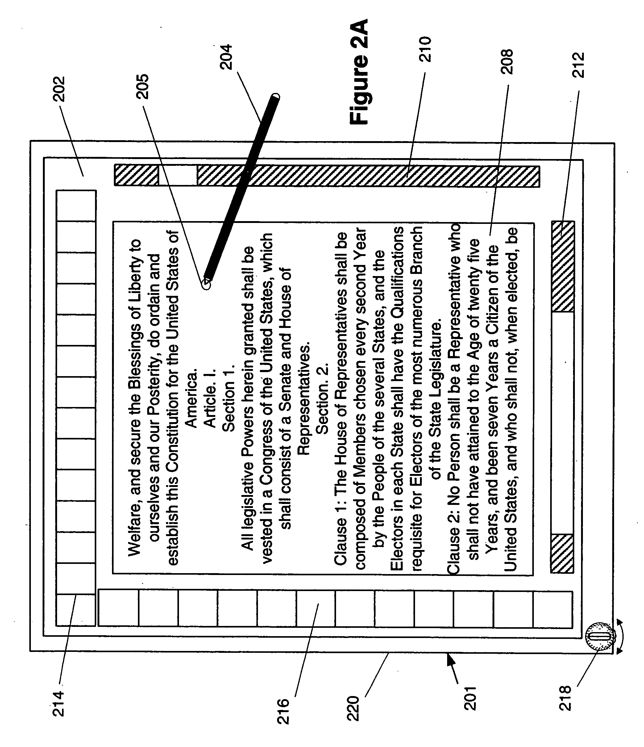
[0009] Further aspects include methods for switching the orientation of an image on a display screen from a first orientation to a second orientation. In other aspects, computer-executable instructions for implementing the disclosed methods are stored on computer-readable media. These and other aspects are addressed in relation to the figures and related description.

Problems solved by technology

However, such a directional input device has limited ability to work in both display orientations.
They are typically arranged for a default display orientation, such as the portrait mode, and do not work well in the alternate display mode.
However, these known switch mechanisms are unduly complicated or do not provide the user with a quick and easy way to switch between the display orientations.
Further, these systems lack indicators that readily identify the current orientation state of the display.

Method used


Image

  • Directional input device and display orientation control
  • Directional input device and display orientation control
  • Directional input device and display orientation control

Examples


Embodiment Construction

[0022] Aspects of the present invention relate to switching display orientations and to directional input devices associated therewith.

[0023] This document is divided into sections to assist the reader. These sections include the followng: Terms, General-purpose computing environment, Directional input device orientation and display orientation control, and Directional input devices.

Terms

[0024] Directional input device—An input device for receiving user input to modify a display in a substantially linear direction using a graphical user interface (GUI) system, such as Microsoft WINDOWS. The input device may receive user input to modify the display in a various linear directions. Modification of the display may include scanning displayed content shown on the display in a user-selected linear direction, such as by scrolling a document, moving a cursor on the display in the selected linear direction, and translating a selected item shown on the display in the selected linear direct...


PUM


Abstract

A computer system includes a processor creating a renderable image in a first orientation, a display showing the image in the first orientation, and a directional input device having an orientation indicator that is movable between a first position associated with the first image orientation and a second position associated with a second image orientation. The orientation indicator may provide a visual indication of the orientation of the image being shown on the display. The orientation indicator may be movable between a first position associated with the first image orientation and a second position associated with a second image orientation. The processor may create the renderable image in the second orientation and the display may show the image in the second orientation in response to the orientation indicator moving from the first position to the second position.

Description

BACKGROUND OF THE INVENTION [0001] 1. Field of the Invention [0002] Aspects of the present invention relate to computer processing and information manipulation. More specifically, aspects of the present invention relate to a directional input device that is associated with orientation of a corresponding display, and to changing the image orientation of a display screen. The invention has application to computing devices having displays with a plurality of orientation modes and to a directional input device, such as a mouse wheel or a touch pad. [0003] 2. Description of Related Art [0004] Typical computer systems, especially computer systems using graphical user interface (GUI) systems such as Microsoft WINDOWS, are optimized for accepting user input from one or more discrete input devices, such as a keyboard for entering text and a pointing device such as a mouse with one or more buttons for driving the user interface. The ubiquitous keyboard and mouse interface provides for fast cr...

Claims


Application Information

Patent Timeline
IPC IPC(8): G06F17/00G06F3/00G06F9/00
CPCG06F1/1626G06F1/169G06F3/0338G06F3/03547G06F3/0362G06F3/0485G06F2200/1614G06F3/00G06F3/14
Inventor KEELY, LEROY B.
Owner MICROSOFT TECH LICENSING LLC
Learn More