Adjustable throw-lever picatinny rail clamp

a technology of swan and rail clamp, which is applied in the direction of construction fastening devices, mechanical devices, fastening means, etc., can solve the problem of not being able to adjust the throw lever of swan

Active Publication Date: 2006-06-15
LARUE MARK C
View PDF11 Cites 78 Cited by
  • Summary
  • Abstract
  • Description
  • Claims
  • Application Information

AI Technical Summary

Benefits of technology

[0005] It is a primary feature of the present invention to provide novel mounting rings for retaining sighting devices, such as telescopes, low light optical devices, mechanical sighting devices on firearms such as rifles and to permit removal and replacement of the sighting devices, even under field conditions, without losing the preset zero of the sighting device;
[0006] It is another feature of the present invention to provide a novel optical sight mounting system which permits one or several daylight, night or close combat optical sighting devices to be selectively interchanged on a firearm in a manner that maintains the preset sighting zero of each of the optical sighting devices with respect to the firearm that is involved; and
[0007] It is also a feature of the present invention to provide a novel optical sight mounting system that employs self-centering and self-aligning optical sight mounting rings that eliminates the need for lapping for achieving a close fit with the tube of an optical sighting device and prevents damage to an optical sighting device by tube distortion from clamping force.

Problems solved by technology

The throw-lever of Swan is not adjustable, though the patent makes incorrect assumptions of its adjustability.

Method used


Image

  • Adjustable throw-lever picatinny rail clamp
  • Adjustable throw-lever picatinny rail clamp
  • Adjustable throw-lever picatinny rail clamp

Examples


Embodiment Construction

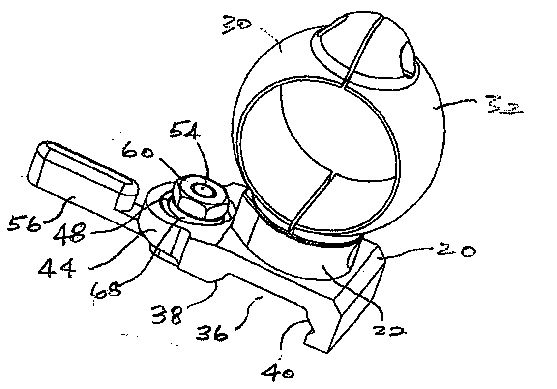
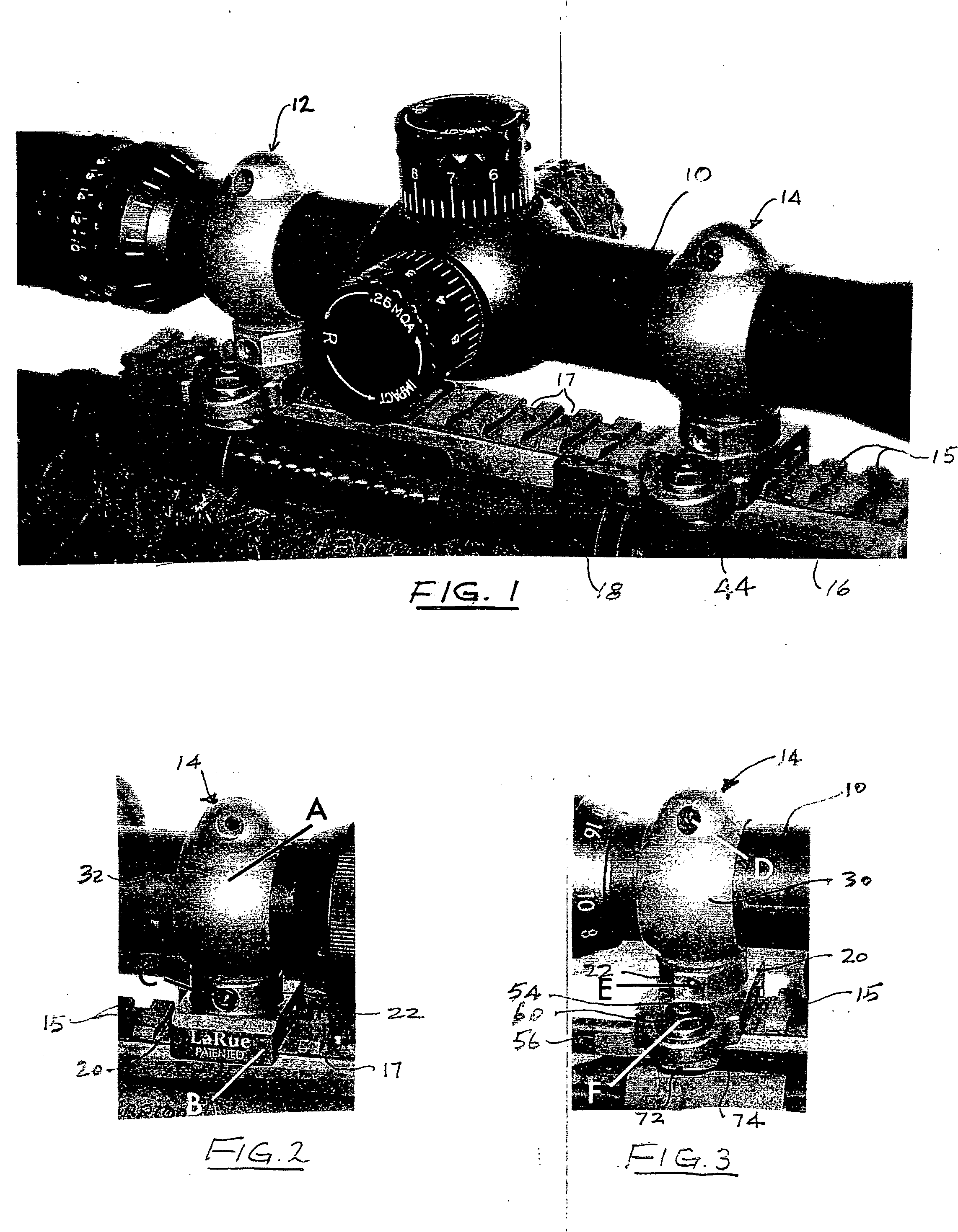
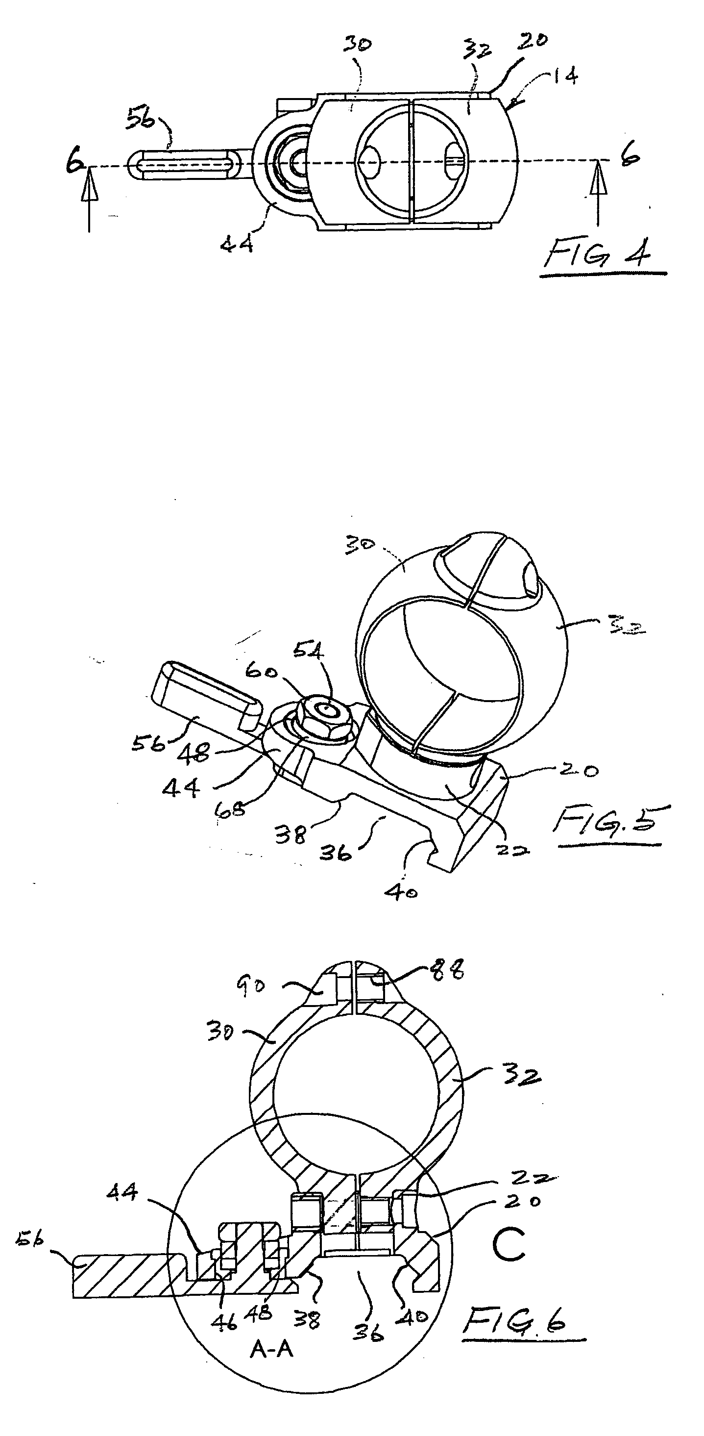
[0037] Though the present invention is discussed herein particularly as it relates to releasable mounts for firearms, particularly tactical rifles used by military and law enforcement personnel, it is to be understood that this invention has application for support of devices other than optical sighting devices on other objects. Referring now to the drawings and first to FIG. 1, an optical sighting device 10, such as a sighting telescope, is supported by front and rear mounting ring assemblies, shown generally at 12 and 14, that mount the sighting device on a mounting rail 16, such as a Picatinny rail or a Weaver rail or the like which is affixed to a firearm 18 or other object. The rail 16 defines a number of evenly spaced upwardly extending mounting projections 15 with evenly spaced transverse slots 17 therebetween to provide for selective location of an optical device on the firearm. As is evident in FIG. 7, each of the spaced upwardly extending mounting projections defines under...


PUM


Abstract

A throw-lever releasable mounting system for mounting a device in quick-release relation to a support member has a mounting base having a configuration fitting opposed angulated rail surfaces and having a locator key engaging a positioning slot of the rail. Each mounting base provides for mounting and stabilization of optics mounting rings. A locking platform projects from the mounting base and defines a locking opening having a circular hard metal insert therein that defines a receptacle receiving a resilient member and providing for location of the spline / spindle shaft of a rotatable locking plate. A locking plate of a throw-lever that is rotatable between locking and unlocking positions has angulated and curved cam surfaces for forcibly engaging correspondingly angulated surfaces of the rail to achieve cam energized precision locating and locking engagement with the rail. A non-circular section of a spline / spindle shaft of the throw-lever is receives a drive member in non-rotatable and linearly moveable relation. Resilient members are interposed between the drive member and the hardened insert and prevent free throw-lever movement at the release position thereof.

Description

BACKGROUND OF THE INVENTION [0001] 1. Field of the Invention [0002] The present invention relates generally to quick-release mounting devices for releasably mounting various devices on a support structure. The present invention also relates to firearms and more particularly to releasable sighting or aiming devices for rifles. More particularly, the present invention concerns mounting devices having adjustable locking mechanisms and mounting rings for releasably securing aiming devices, such as the sighting telescopes of rifles and similar firearms and for maintaining optimum sighting accuracy even when the firearm is subjected to repeated heavy recoil when firing high velocity, large bore ammunition. Even more particularly, the present invention concerns locking type mounting rings that enable rifle sighting devices to be simply and efficiently removable and replaceable under field conditions while maintaining a preset zero when replaced. [0003] 2. Description of the Prior Art [0004...

Claims


Application Information

Patent Timeline
Patent Type & Authority Applications(United States)
IPC IPC(8): F41G1/38
CPCF41G11/003Y10T292/0847Y10T292/0998Y10T292/1022Y10T292/1033
Inventor LARUE, MARK C.
Owner LARUE MARK C
Why Eureka
Try Eureka