Desinfection device for a cryostat

a cryostat and desinfection device technology, applied in the field of cryostats, can solve the problems of inability to complete cleaning and/or disinfection, and inability to cut waste, etc., to achieve the effect of improving the cleaning and/or disinfection procedur

Inactive Publication Date: 2006-06-15
LEICA BIOSYST NUSSLOCH
View PDF17 Cites 8 Cited by
  • Summary
  • Abstract
  • Description
  • Claims
  • Application Information

AI Technical Summary

Benefits of technology

[0010] It is therefore the object of the present invention to improve the cleaning and/or disi...

Problems solved by technology

Cutting waste also inevitably occurs during microtome operation, and must be removed from the cryostat from time to time.
This manual method has proven successful, but of course is very time-consuming.
This waste pan e...

Method used


Image

  • Desinfection device for a cryostat
  • Desinfection device for a cryostat
  • Desinfection device for a cryostat

Examples


Embodiment Construction

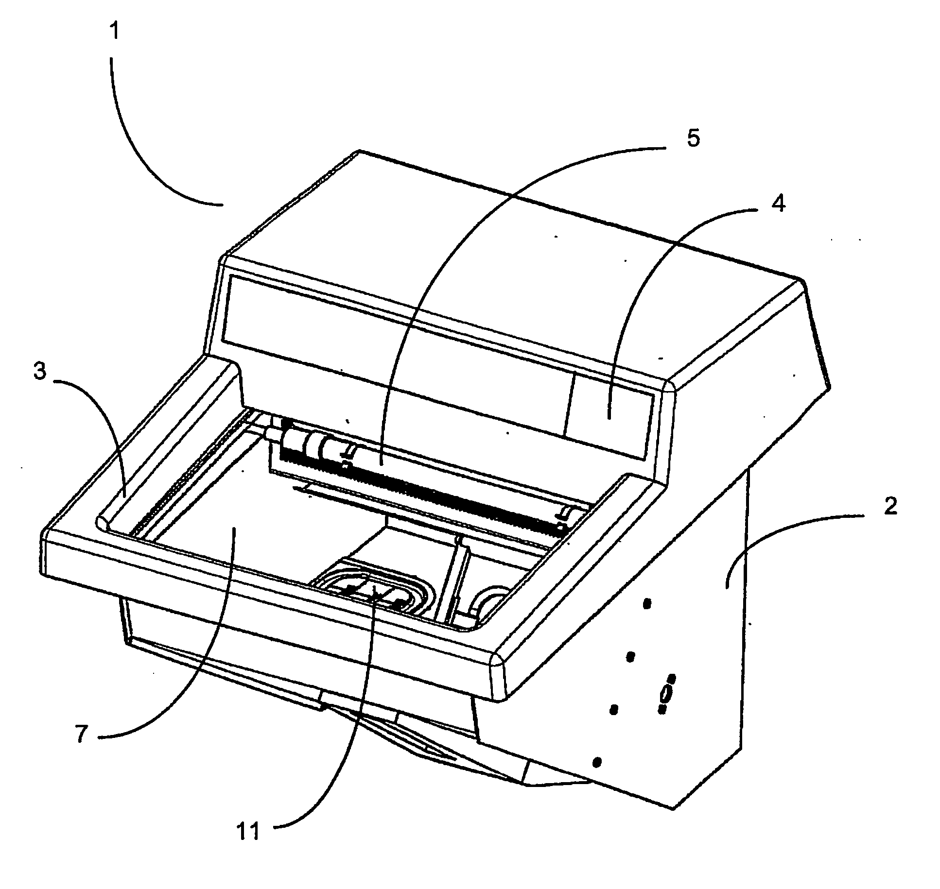
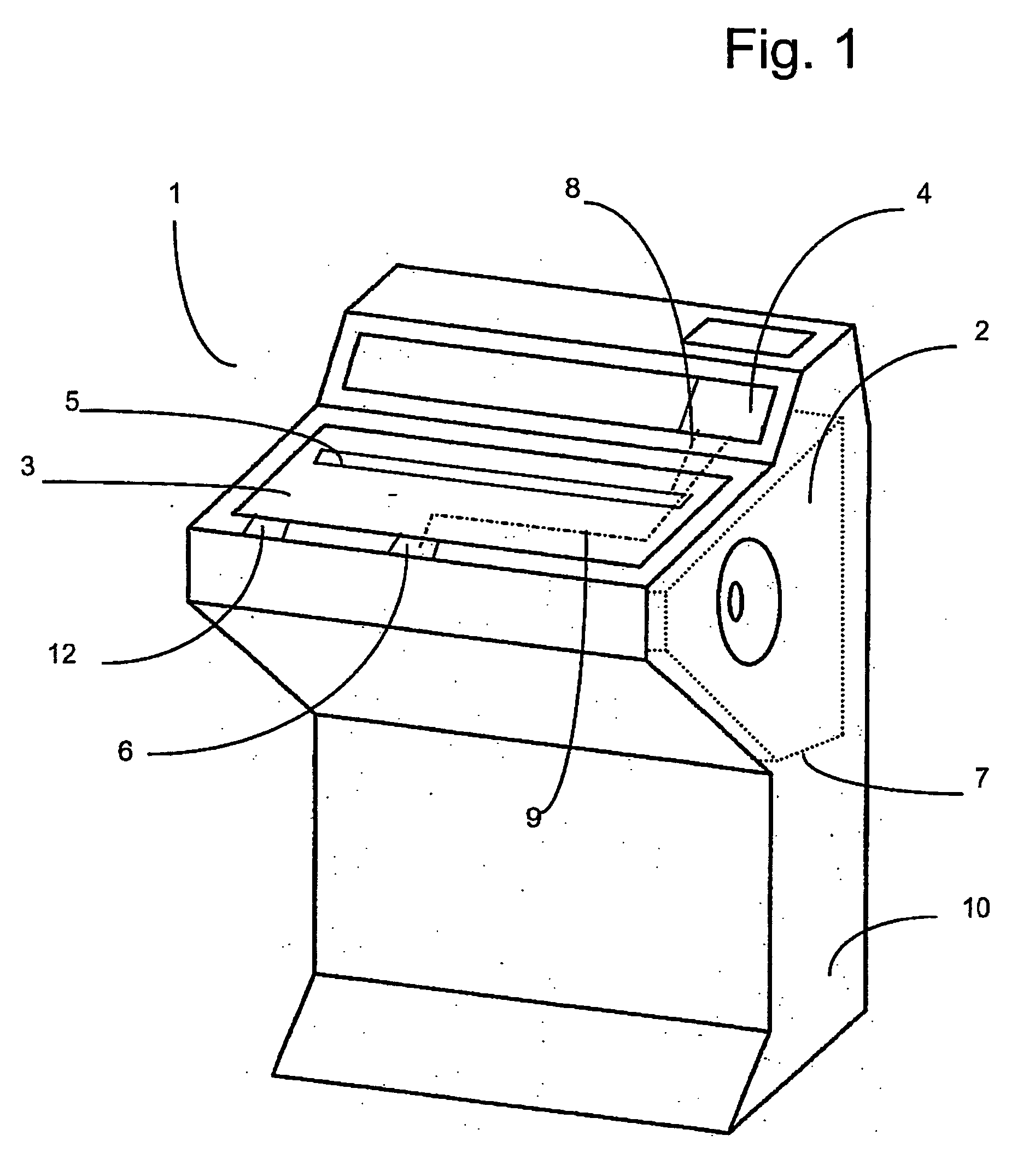
[0021]FIG. 1 is a view of cryostat 1 having a housing 10 and a container 2 arranged in housing 10. Container 2 serves to receive a microtome (not depicted) having a cutting knife. A UV-C light source 5 is fixedly arranged in the interior of the container and connected via an electrical line 8 to a control circuit 4. A cover 3 closing off container 2 is arranged on housing 10. Arranged between housing 10 and cover 3 is a safety switch 6 that is electrically connected via a line 9 to control circuit 4. Also associated with cover 3 is an electrically operating locking system 12.

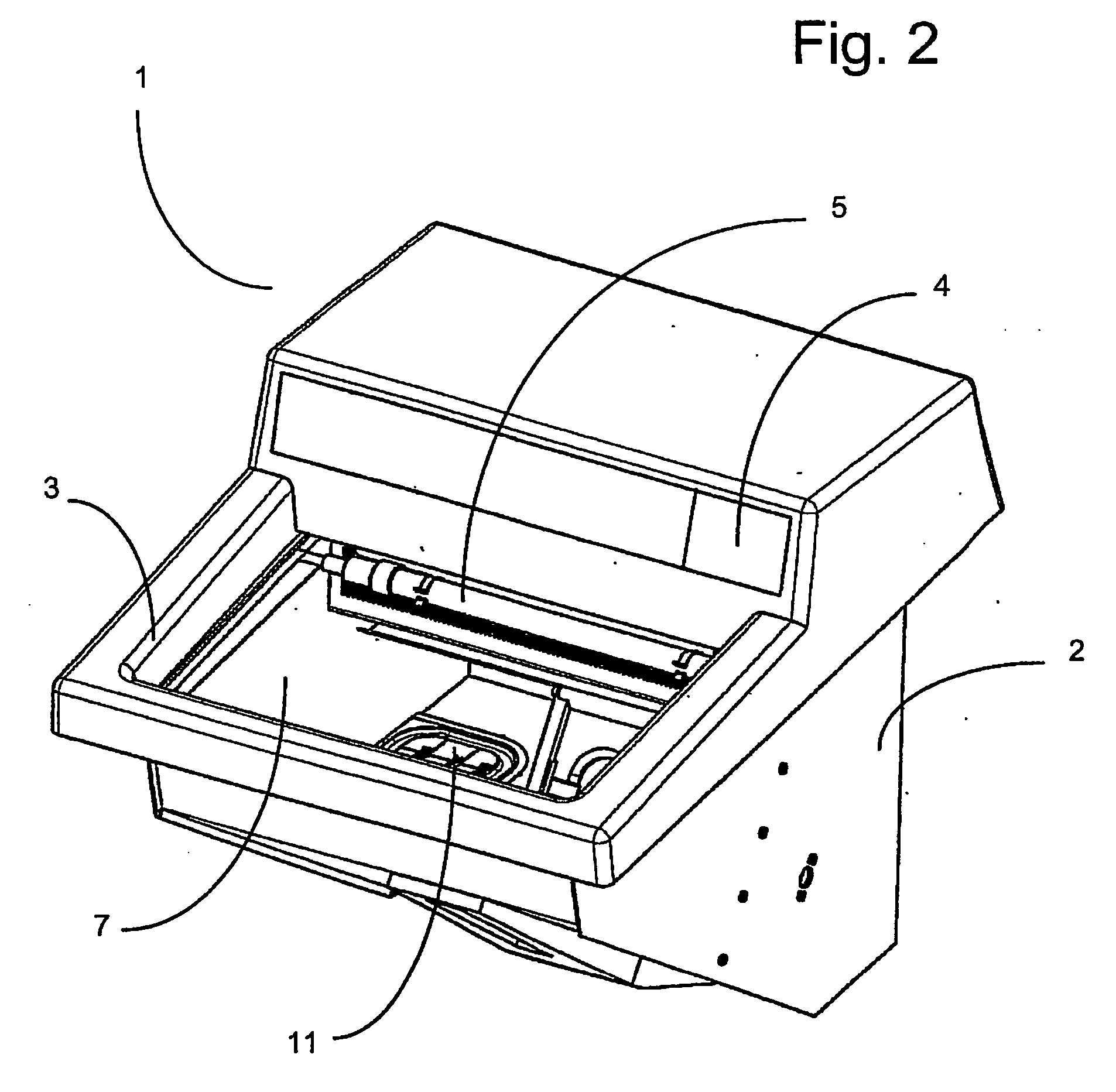
[0022]FIG. 2 shows container 2 having UV-C light source 5 arranged therein, and a cooling device 11. Container 2 comprises on its inner side a coating 7. Coating 7 contains titanium dioxide nanoparticles as well as, additionally, silver ion nanoparticles.

[0023] For disinfection of container 2, UV-C light source 5 is started manually or automatically, via a timer integrated into control circuit 4, for a presele...


PUM


Abstract

A cryostat (1) having a container (2) for receiving a microtome is described, having a cover (3) closing off the container (2) and having a disinfection device associated with which is a control circuit (4). The microtome comprises a knife holder, and the disinfection device is equipped with a UV light source (5).

Description

CROSS REFERENCE TO RELATED APPLICATIONS [0001] This application claims priority of the German patent application 10 2004 056 189.3 which is incorporated by reference herein. FIELD OF THE INVENTION [0002] The present invention relates to a cryostat of a type having a container for receiving a microtome, the microtome comprising a knife holder; the cryostat having a cover for closing off the container, a disinfection device, and a control circuit associated with the disinfection device. BACKGROUND OF THE INVENTION [0003] Cryostat microtomes are designed to cool the specimens that are to be cut to a specific predefined temperature. The temperatures are as a rule between −10° C. and −50° C. In order to guarantee temperature consistency, the microtomes are arranged in complex encapsulated housings. A stainless-steel container to receive the microtome is provided in the interior of the housing. The cryostat furthermore comprises a closable viewing window or a cover, through which the user...

Claims


Application Information

Patent Timeline
IPC IPC(8): F25B19/00F25D23/00A61L2/10G01N1/06
CPCA61L2/10G01N1/06F17C3/085G01N1/44
Inventor METZNER, ROLF
Owner LEICA BIOSYST NUSSLOCH
Why Eureka
Try Eureka