
System and method for measuring flow

Inactive Publication Date: 2006-06-15
BROOKS INSTRUMENT
View PDF25 Cites 20 Cited by
  • Summary
  • Abstract
  • Description
  • Claims
  • Application Information

AI Technical Summary

Benefits of technology

[0006] Embodiments of the present invention provide systems and methods for measuring flow that substantially reduce or eliminate the disadvantages associated with previously developed flow measurement methods and systems. More particularly, embodiments of the present invention provide a system and method for measuring fluid flow across a range of flow rates by combining the features of a primary flow measurement technique with those of a secondary flow measurement technique in order to cover a wider range of dynamic flows.
[0010] Embodiments of the present invention, thus, can use primary measurement techniques to attain accurate measurement capabilities while using secondary techniques to extend the flow measurement range of the primary technique. Because embodiments of the present invention use multiple flow measurement techniques, the present invention can provide a flow measurement system that is self-calibrating and scalable to a wide range of flows.
[0012] Embodiments of present invention provide another advantage by providing a system for calibrating a secondary flow measurement system based on measurements from a primary flow measurement system. Because the secondary flow measurement system (e.g. sonic nozzle system) can be recalibrated in real time based on flow measurements from the primary technique (e.g. constant volume system), the secondary flow measurement system does not have to be removed from the flow measurement system to be recalibrated.
[0014] Embodiments of the present invention provide yet another advantage over previously developed flow measurement systems and methods by extending the range of primary flow measurement techniques through the use of a secondary flow measurement technique.

Problems solved by technology

Gravimetric techniques are generally sufficient for measuring higher rate flows where mass loss is significant, but suffer shortcomings in measuring lower rate flows because they typically have insufficient resolution to measure mass flow rates on the order of micro-moles per minute.
Thus, the constant pressure technique suffers limitations in calibrating mass flow controllers because constructing a constant pressure chamber (i.e. a variable volume chamber) can require a significant number of moving parts that can cause mechanical complications.
As the range of mass flow rates for which the constant pressure chamber is configured increases, the complexity and cost of the constant pressure system will also increase.
Again, however, the constant volume technique suffers deficiencies for calibrating mass flow controllers because the constant volume technique can typically only be used over a small range of mass flow rates.
This limitation exists because, if the flow rate is too high for a given chamber volume, pressure changes associated with the high mass flow rate will be too abrupt to be accurately measured and may quickly exceed the safety limitations of the chamber.
Although larger constant volume chambers can be constructed, practical considerations of safety, space and cost establish an upper limit on the capability of this flow measurement technique.
In general, the disadvantage of primary flow measurement techniques is that each technique is limited to a particular flow range where that technique's uncertainties and design limitations are best suited.

Method used


Image

  • System and method for measuring flow
  • System and method for measuring flow
  • System and method for measuring flow

Examples


Embodiment Construction

[0020] Preferred embodiments of the present invention are illustrated in the FIGURES, like numerals being used to refer to like and corresponding parts of the drawings.

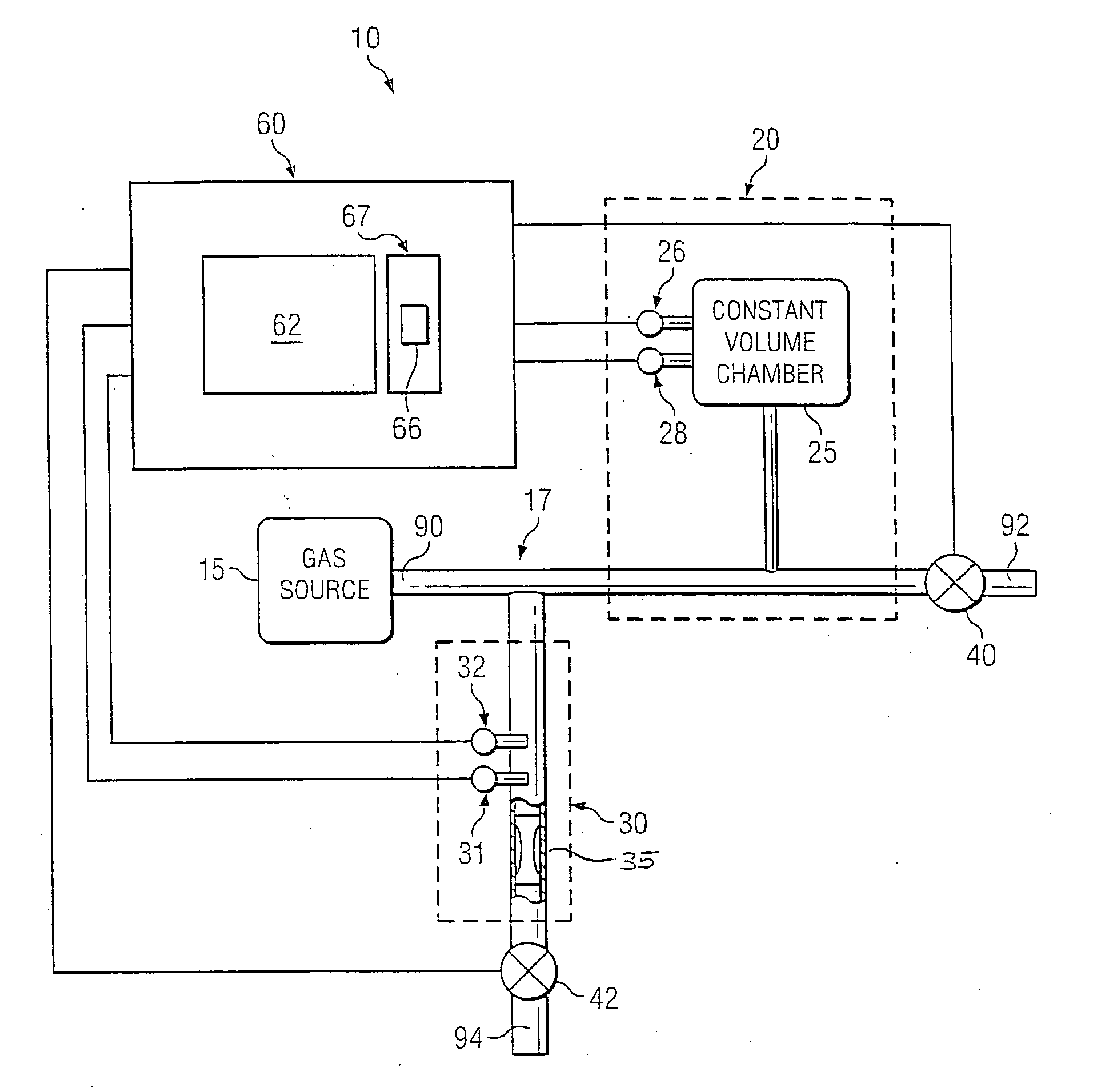
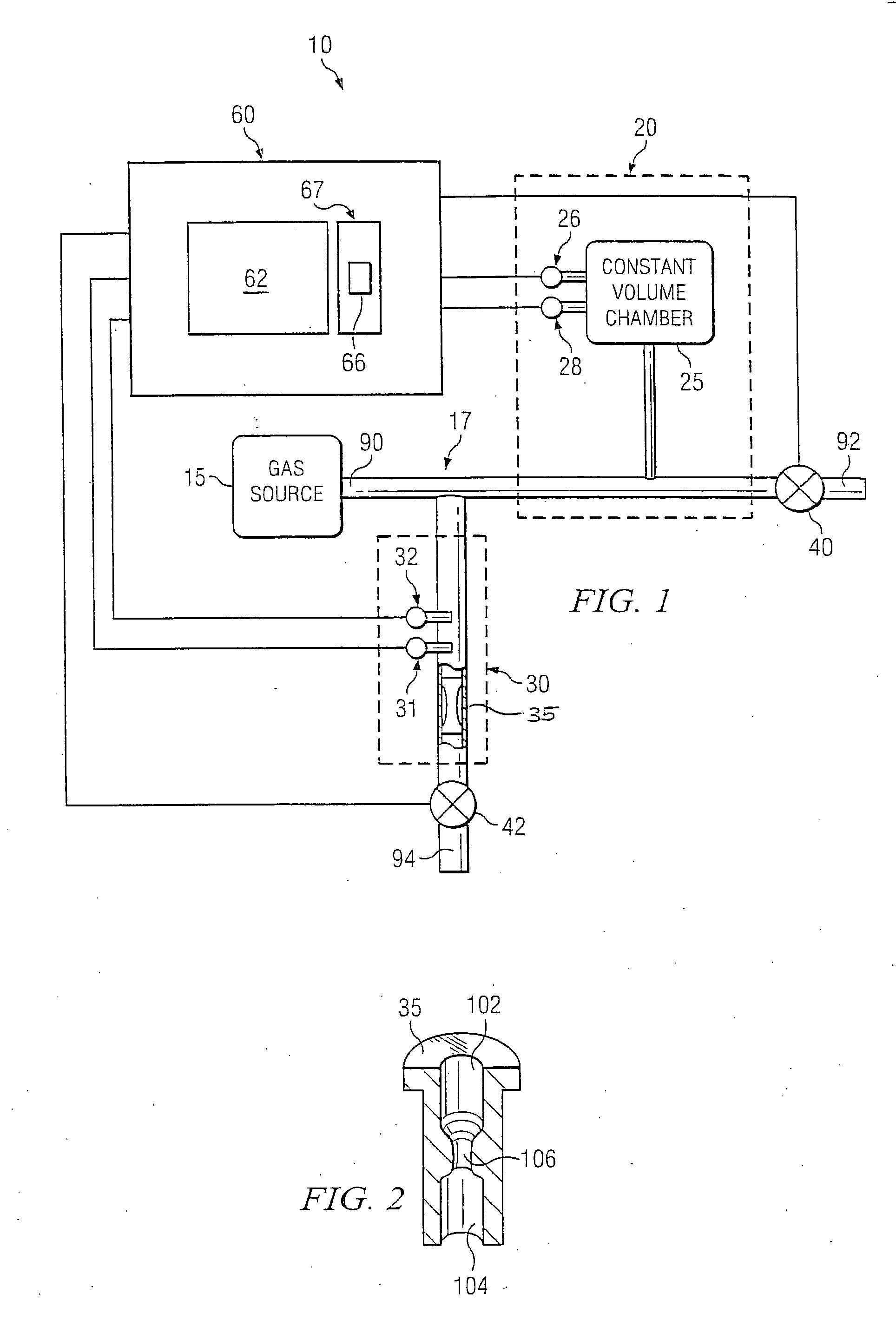
[0021] Embodiments of the present invention provide a system and method for measuring the flow rate of a fluid (e.g., a liquid, a gas, a gas vapor mix or other fluid) across a range of flow rates by combining the features of a primary flow measurement technique with those of a secondary flow measurement technique. In one embodiment of the present invention, a primary flow measurement system (e.g., a constant pressure system, a constant volume system, a gravimetric measurement system or other primary flow measurement system known in the art) can be in fluid communication with a secondary flow measurement system (e.g., a sonic nozzle system, a laminar flow meter, an ultrasonic flow meter, a coriolis flow meter, a thermal mass flow meter or other secondary flow measurement system known in the art). A controller can rece...


PUM


Abstract

One embodiment of the present invention can comprise a primary flow measurement system, a secondary flow measurement system in fluid communication with the primary flow measurement system and a control coupled to the primary flow measurement system and the secondary flow measurement system. The controller can comprise a processor and a memory accessible by the processor. The processor can execute computer instructions stored on the memory to calculate a flow rate using the primary flow measurement system, in a first mode of operation, and calculate the flow rate using the secondary flow measurement system, in a second mode of operation. The computer instructions can be further executable to switch between the first mode of operation and the second mode of operation based on a predefined parameter.

Description

TECHNICAL FIELD OF THE INVENTION [0001] Embodiments of the present invention relate generally to flow measuring systems and more particularly to a system and method for measuring a flow utilizing both a primary flow measurement technique and a secondary flow measurement technique. BACKGROUND [0002] A number of flow measurement techniques are currently used to calibrate mass flow controllers. Primary flow measurement techniques, which derive their accuracy from constants of nature or from other primary measurements such as mass and time, include gravimetric techniques, constant pressure techniques and constant volume techniques. The first primary technique, gravimetric measurement, involves measuring the amount of mass either gained or lost over a time interval. Gravimetric techniques are generally sufficient for measuring higher rate flows where mass loss is significant, but suffer shortcomings in measuring lower rate flows because they typically have insufficient resolution to meas...

Claims


Application Information

Patent Timeline
IPC IPC(8): G01F1/00
CPCG01F7/005G05D13/00
Inventor TISON, STUART A.LU, SHILIANG
Owner BROOKS INSTRUMENT
Learn More