
Method for signal enhancement in azimuthal propagation resistivity while drilling

Inactive Publication Date: 2006-06-15
BAKER HUGHES INC
View PDF8 Cites 62 Cited by
  • Summary
  • Abstract
  • Description
  • Claims
  • Application Information

AI Technical Summary

Benefits of technology

[0012] One embodiment of the invention is a method of determining a resistivity of an earth formation. A logging tool is conveyed into a borehole in the earth formation. At least one principal cross-component measurements is obtained at each of a plurality of tool-face angles. The resistivity is determined from the measurements correcting for a bias in the measurements. The determination may be made using a sinusoidal curve fitting. The principal cros

Problems solved by technology

A limitation of the method and apparatus used by Wu is that resistivity sensors are responsive to oil / water contacts for relatively small distances, typically no more than 5 m; at larger distances, conventional propagation tools are not responsive to the resistivity contrast between water and oil.

Method used


Image

  • Method for signal enhancement in azimuthal propagation resistivity while drilling
  • Method for signal enhancement in azimuthal propagation resistivity while drilling
  • Method for signal enhancement in azimuthal propagation resistivity while drilling

Examples


Embodiment Construction

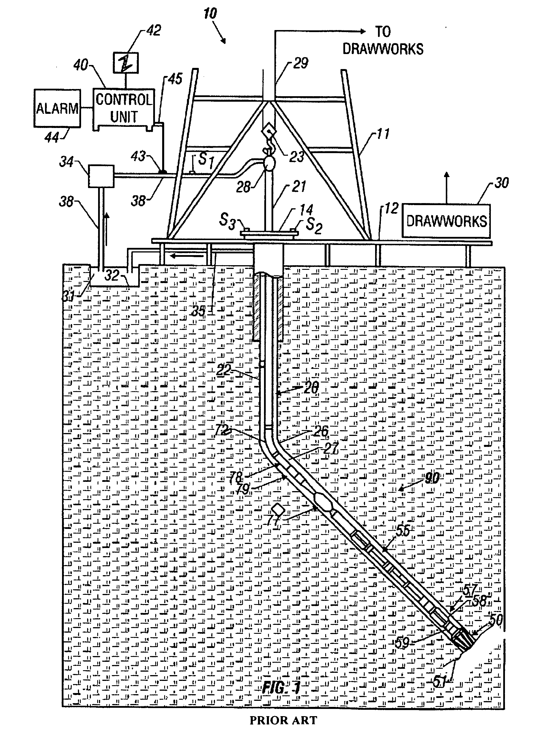
[0028]FIG. 1 shows a schematic diagram of a drilling system 10 with a drillstring 20 carrying a drilling assembly 90 (also referred to as the bottomhole assembly, or “BHA”) conveyed in a “wellbore” or “borehole”26 for drilling the wellbore. The drilling system 10 includes a conventional derrick 11 erected on a floor 12 which supports a rotary table 14 that is rotated by a prime mover such as an electric motor (not shown) at a desired rotational speed. The drillstring 20 includes a tubing such as a drill pipe 22 or a coiled-tubing extending downward from the surface into the borehole 26. The drillstring 20 is pushed into the wellbore 26 when a drill pipe 22 is used as the tubing. For coiled-tubing applications, a tubing injector, such as an injector (not shown), however, is used to move the tubing from a source thereof, such as a reel (not shown), to the wellbore 26. As would be known to those versed in the art, with coiled tubing, a rotary table is not used. The drill bit 50 attache...


PUM


Abstract

Cross-component measurements made at a plurality of toolface angles are processed to remove bias. The amplitude of the resulting sinusoid is used to estimate a distance to an interface in an earth formation.

Description

CROSS-REFERENCES TO RELATED APPLICATIONS [0001] This application is a continuation-in-part of U.S. patent application Ser. No. 10 / 373,365 filed on Feb. 24, 2003, which was a continuation-in-part of U.S. patent application Ser. No. 10 / 214,436 filed on Aug. 7, 2002 and also claimed priority from U.S. Provisional Patent Application Ser. No. 60 / 361,570 filed on Mar. 4, 2002.BACKGROUND OF THE INVENTION [0002] 1. Field of the Invention [0003] This invention relates generally to drilling of lateral wells into earth formations, and more particularly to the maintaining the wells in a desired position relative to an interface within a reservoir by making measurements during rotation of the bottomhole assembly. [0004] 2. Description of the Related Art [0005] To obtain hydrocarbons such as oil and gas, well boreholes are drilled by rotating a drill bit attached at a drill string end. The drill string may be a jointed rotatable pipe or a coiled tube. Boreholes may be drilled vertically, but dire...

Claims


Application Information

Patent Timeline
IPC IPC(8): G01V3/18
CPCE21B47/022G01V3/28E21B49/00G01V3/18
Inventor CHEMALI, ROLAND E.CAIRNS, PAULWANG, TSILIMEYER, WALLACE H.BROOKS, ANDREWFANINI, OTTOMERCHANT, GULAMABBAS
Owner BAKER HUGHES INC
Learn More