Optical deflector

Active Publication Date: 2006-06-15
OLYMPUS CORP
View PDF3 Cites 13 Cited by
  • Summary
  • Abstract
  • Description
  • Claims
  • Application Information

AI Technical Summary

Benefits of technology

[0017] The optical deflector according to the present invention includes a movable plate, a fixed portion which is positioned on an outer side of the movable plate, and the elastic supporting member which is disposed substantially symmetrically about the center line of the movable plate and which connects the movable plate and the fixed portion. The angular-displacement detecting portion detects the angular displacement of the movable plate. The angular-displacement detecting portion has the Wheatston bridge as a measuring portion which includes the plurality of resistor elements. In this case, at least one r

Problems solved by technology

If the strain gauges which form the Wheatston bridge circuits are at positions away from each other, it is susceptible to influence of a surrounding temperature d

Method used


Image

  • Optical deflector
  • Optical deflector
  • Optical deflector

Examples


Example

FIRST EMBODIMENT

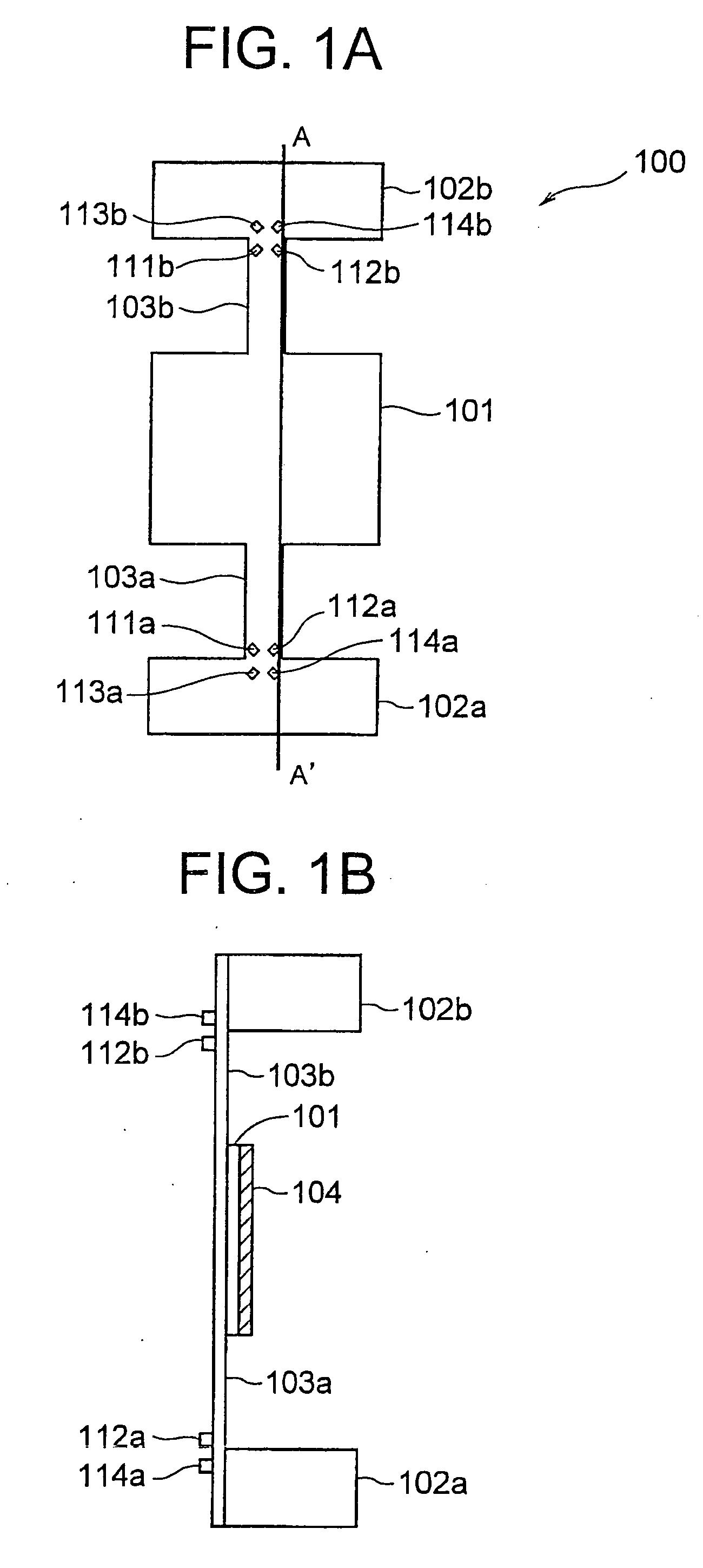
[0037]FIG. 1A denotes a schematic front view of an optical deflector 100 according to a first embodiment of the present invention. FIG. 1B denotes a cross-sectional view along a line A-A′. The structure is such that an elastic supporting portion 103a is extended from a fixed portion 102a. Moreover, an elastic supporting portion 103b is extended from the other fixed portion 102b. A movable plate 101 is formed on an opposite side of a side of the elastic supporting portions 103a and 103b to which the fixed portions 102a and 102b are connected. A mirror surface 104 is formed on a rear surface of the movable plate 101. The mirror surface 104 is made of a material such as aluminum.

[0038] Two active resistors 111a and 112a are formed near a portion (near a connecting portion) on the elastic supporting portion 103a where the fixed portion 102a is connected. Moreover, two reference resistors 113a and 114a are formed near a portion (near a connecting portion) on the fixed p...

Example

SECOND EMBODIMENT

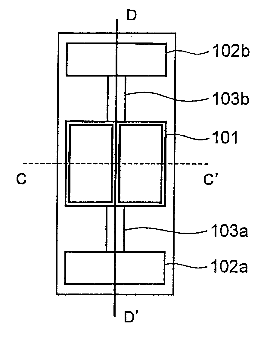
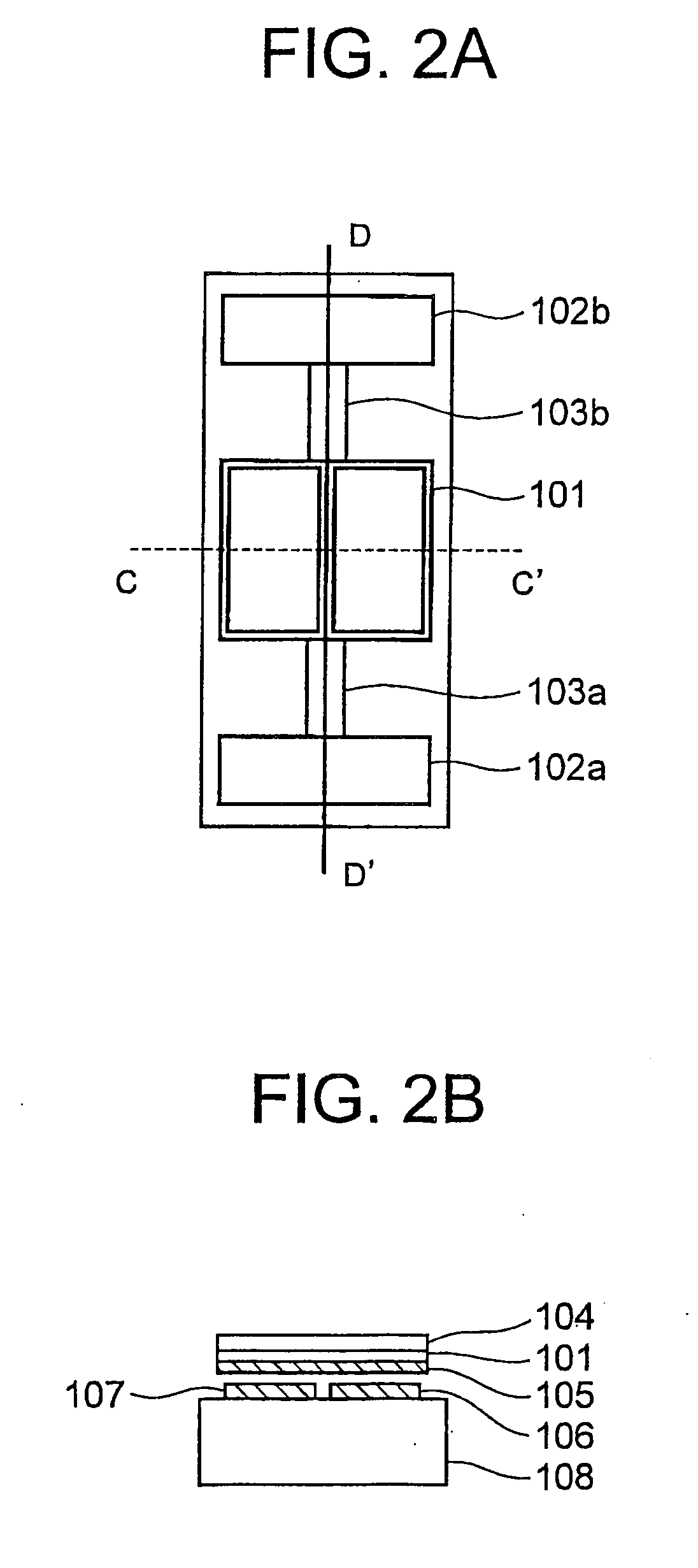
[0057]FIG. 5A denotes a schematic front view of an optical deflector 200 according to a second embodiment of the present invention. FIG. 5B denotes a cross-sectional view of FIG. 5A taken along a line E-E′. Same reference numerals are used for portions identical with the portions in the first embodiment.

[0058] The two elastic supporting portions 103a and 103b are extended from the fixed portions 102a and 102b respectively. The movable plate 101 is formed on the opposite side of the side of the elastic supporting portions 103a and 103b to which the fixed portions 102a and 102b are connected. The mirror surface 104 is formed on the rear surface of the movable plate 101. The mirror surface 104 is made of a material such as aluminum.

[0059] The two active resistors 111a and 112a are formed near the portion (near the connecting portion) of the elastic supporting portion 103a where the fixed portion 102a is connected. Moreover, the two reference resistors 113a and 114a ...

Example

THIRD EMBODIMENT

[0067]FIG. 6A denotes a schematic front view of an optical deflector 300 according to a third embodiment of the present invention. FIG. 6B denotes a cross-sectional view taken along a line F-F′ in FIG. 6A. Same reference numerals are used for portions identical with the portions in the first embodiment.

[0068] The two elastic supporting portions 103a and 103b are extended from the fixed portions 102a and 102b respectively. The movable plate 101 is formed on the opposite side of the side of the elastic supporting portions 103a and 103b to which the fixed portions 102a and 102b are connected. The mirror surface 104 is formed on the rear surface of the movable plate 101. The mirror surface 104 is made of a material such as aluminum.

[0069] An active resistor 611a is formed near a portion (near the connecting portion) on the elastic supporting portion 103 where the fixed portion 102a is connected. Moreover, three reference resistors 612a, 613a, and 614a are formed near ...


PUM


Abstract

The present invention provides an optical deflector which is capable of reducing a temperature drift of a strain gauge due to a temperature gradient, and detecting with high accuracy an angular displacement of a mirror surface. The optical deflector which deflects light includes a movable plate, two fixed portions which are disposed at an outer side of the movable plate, two elastic supporting members which are disposed such that the elastic supporting members are substantially symmetric about a center line of the movable plate, and which connect the movable plate and the two fixed portions, an angular-displacement detecting portion having a Wheatston bridge as a measuring portion which includes two active resistors, and two reference resistors, and detects an angular displacement of the movable plate, and at least one resistor element, such as the two active resistors are provided on the elastic supporting portion. In the optical deflector, all the four resistor elements are in an isothermal characteristics area which is an area in which all the resistor elements are at approximately the same temperature condition.

Description

CROSS-REFERENCE TO RELATED APPLICATION [0001] The present application is based upon and claims the benefit of priority from the prior Japanese Patent Application No. 2004-361208 filed on Dec. 14, 2004; the entire contents of which are incorporated herein by reference. BACKGROUND OF THE INVENTION [0002] 1. Field of the Invention [0003] The present invention relates to an optical deflector, and in particular to an optical deflector which includes an angular-displacement detecting portion. [0004] 2. Description of the Related Art [0005] In recent years, an optical deflector which is manufactured by using a micro machine technology in which a semiconductor manufacturing technology is applied has been drawing attention. For example, in Japanese Patent Application Laid-open Publication No. Hei 5-119280, an optical deflector which is used in a scanner of a projection display and a laser printer, has been disclosed. [0006]FIG. 12 denotes a structure of an optical deflector disclosed in Japa...

Claims


Application Information

Patent Timeline
IPC IPC(8): H01C10/32
CPCG02B26/0833H01C10/345
Inventor KAMIYA, YOSHITAKAMURAKAMI, KENZIMATSUO, DAISUKEOKA, YOSUKE
Owner OLYMPUS CORP
Why Eureka
Try Eureka