Lenticular lens sheet, rear projection type screen, and rear projection type projector, and lenticular lens sheet producing method

Inactive Publication Date: 2006-06-15
KURARAY CO LTD
View PDF7 Cites 14 Cited by
  • Summary
  • Abstract
  • Description
  • Claims
  • Application Information

AI Technical Summary

Benefits of technology

[0012] The present invention has been accomplished to solve the above problems and an object of the present invention is thus to provide a lenticular lens sheet, a rear projection screen, and a rear projection apparatus which improve

Problems solved by technology

Thus, diffusion material used to obtain the required vertical viewing angle causes reflection loss of input light, which poses a fundamental limitation to obtain a high brightness screen and makes images out of focus.
Furthermore, the ambient light absorbing layer 4 is fundamentally restricted to the form of stripe, which poses a limitation to an obtained black area ratio.
However, manufacture of the fine three-dimensional lens array sheet requires a highly accurate and large-scale mold, and it is extremely difficult to produce such a mold; therefore, this sheet has not been realized yet.
However, if the ambient light absorbing layer is formed in a different sheet from the lenticular lens sheet, the relative positio

Method used


Image

  • Lenticular lens sheet, rear projection type screen, and rear projection type projector, and lenticular lens sheet producing method
  • Lenticular lens sheet, rear projection type screen, and rear projection type projector, and lenticular lens sheet producing method
  • Lenticular lens sheet, rear projection type screen, and rear projection type projector, and lenticular lens sheet producing method

Examples


embodiment 1

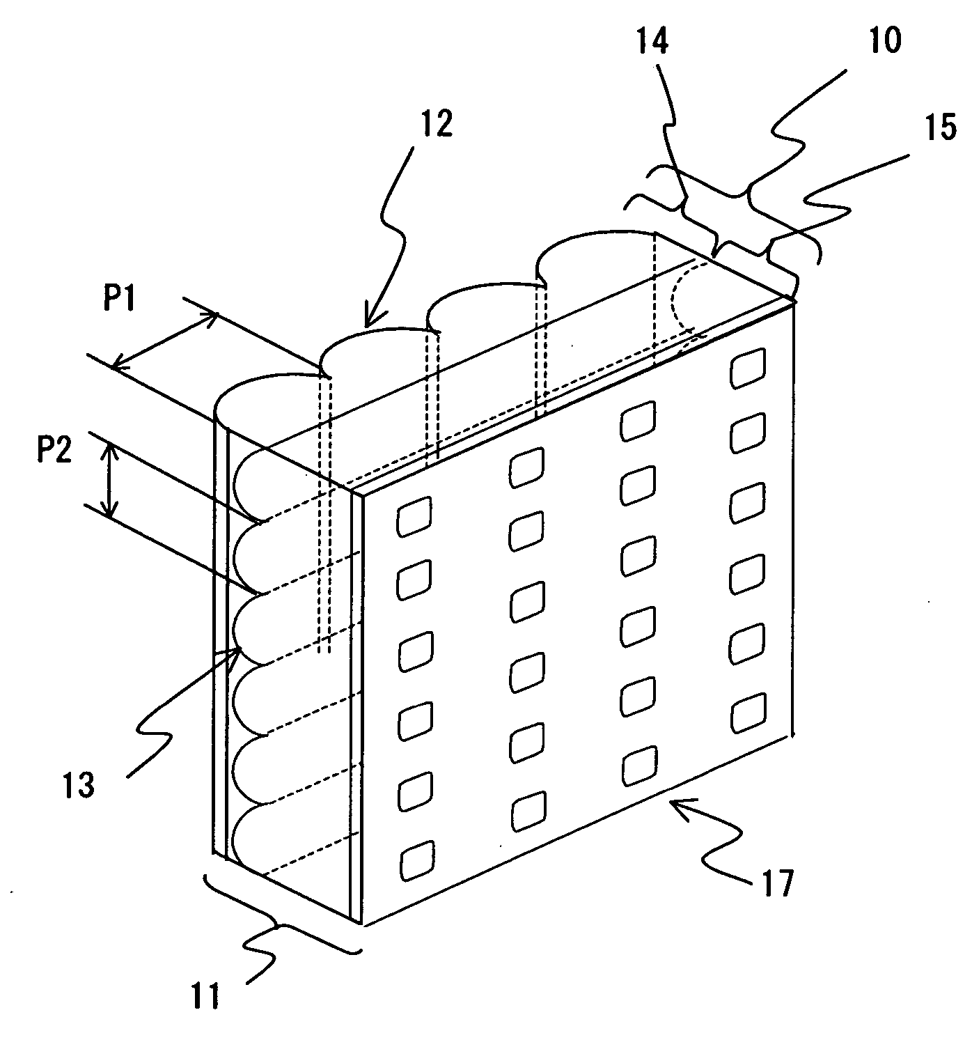
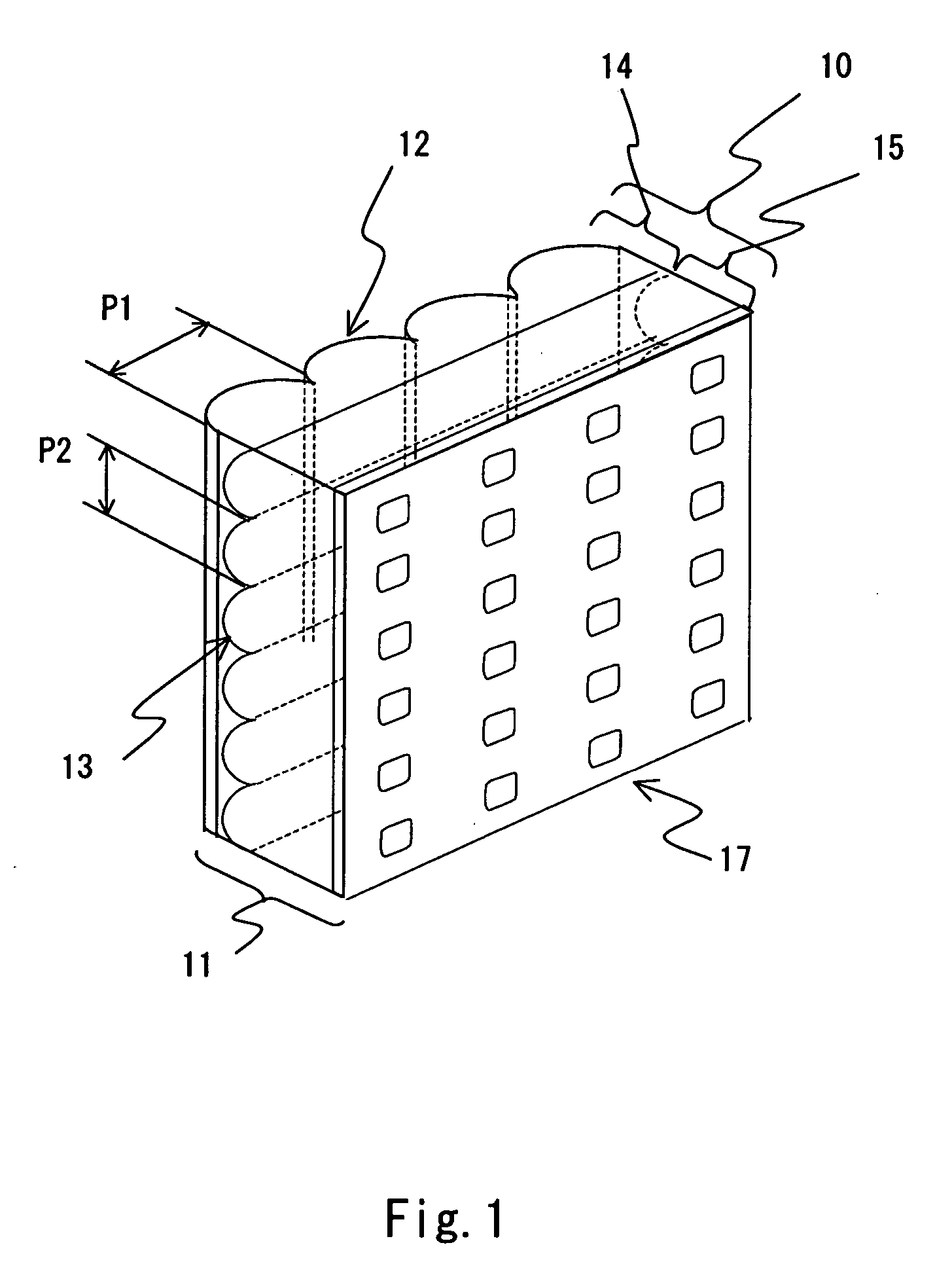
[0045]FIG. 1 is a perspective view showing the structure of a principal part of a lenticular lens sheet according to a first embodiment of the invention. Regarding the lenticular lens sheet, the structure which does not include a self-aligned ambient light absorbing layer 17 is referred to as a lenticular lens sheet A (reference number 10), and a sheet where the self-aligned ambient light absorbing layer 17 is provided for the lenticular lens sheet A is referred to as a lenticular lens sheet B (reference number 11) in the following description.

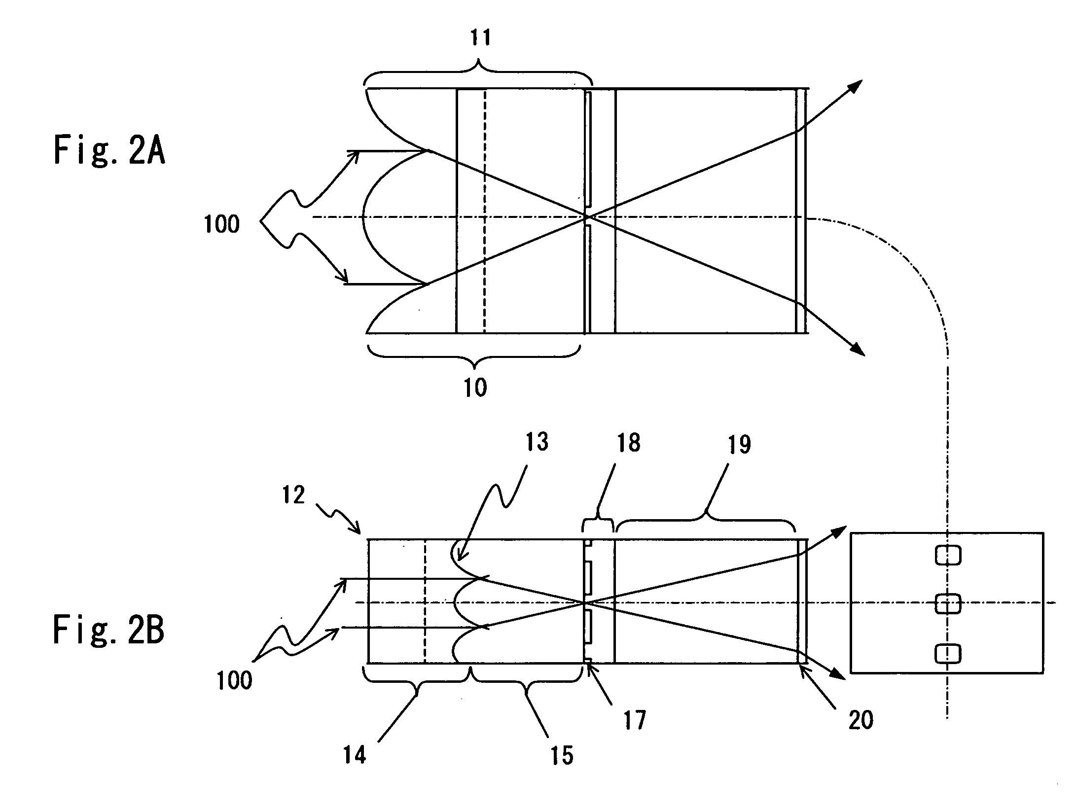
[0046] The lenticular lens sheet A is a lenticular lens sheet in which a first lens layer 14 and a second lens layer 15 having different refractive index from each other are integrated together with a second lens array 13 as a boundary surface. In the first embodiment of the invention, the refractive index of the first lens layer 14 is lower than the refractive index of the second lens layer 15.

[0047] A first lens array 12 is formed on a lig...

embodiment 2

[0069]FIG. 3A is a perspective view showing the structure of a principal part of a rear projection screen according to the second embodiment of the invention. The rear projection screen of the second embodiment is different from that of the first embodiment in the relationship between the refractive indexes of the first lens layer 14 and the second lens layer 15. It has an opposite structure that the refractive index of the first lens layer 14 is higher than that of the second lens layer 15. Thus, the output light having passed through the second lens array 13 does not focus in the vertical direction within the lens medium, and the self-aligned ambient light absorbing layer 17 is stripe-shaped. In the example shown in FIG. 3A, the self-aligned ambient light absorbing layer 17 has a uniform line width and a linear boundary between an ambient light absorbing layer and a light transmission part. However, depending on optical design such as a lens shape, the line width can change period...

embodiment 3

[0075]FIG. 5 is a perspective view showing the structure of a principal part of a rear projection screen according to a third embodiment of the present invention. The rear projection screen of the third embodiment is different from that of the first embodiment in the shape of the second lens array 13 of the lenticular lens sheet A. Specifically, in the third embodiment, the second lens array 13 is formed in such a way that the cross section has a sine waveform. Further, in the rear projection screen of the third embodiment, the shape of the self-aligned ambient light absorbing layer 17 is stripe-shaped just like in the second embodiment. Also just like in the second embodiment, the lens pitch P2 of the second lens array 13 in the third embodiment may be set arbitrarily with respect to the lens pitch P1 of the first lens array 12. Furthermore, the second lens array 13 may have a prism shape or may be a complex lens array composed of a combination of lenses with different curvatures. ...


PUM


Abstract

The rear projection screen of the present invention has a lenticular lens sheet 1. In the input surface of the lenticular lens sheet 1, a first lens array 12 is formed on a first lens layer 14. In the boundary between the first lens layer 14 and a second lens layer 15, a second lens array 13 substantially orthogonal to the first lens array 12 is formed. The second lens layer 15 has a different refractive index from the first lens layer 14. A lattice-shaped or stripe-shaped self-aligned ambient light absorbing layer 17 is formed in a light non-passing position on the second lens layer 15.

Description

TECHNICAL FIELD [0001] The present invention relates to a lenticular lens sheet, a rear projection screen, a rear projection apparatus, and a method of manufacturing a lenticular lens sheet. BACKGROUND ART [0002] A rear projection screen used in a rear projection apparatus or the like normally has a structure where two lens sheets are placed on top of each other. Specifically, a Fresnel lens sheet which narrows down the video light from a rear projection projector within a certain angle range are placed in light source side, and a lenticular lens sheet which has a function to spread the video light transmitted through the Fresnel lens sheet over an appropriate angle range is placed in observer side. [0003] Particularly, very fine and high quality rear projection liquid crystal projection television requires a lens sheet with fine pitch of 0.3 mm or smaller. The structure of such a lens sheet is disclosed in Japanese Unexamined Patent Publication No. 09-120101, for example. FIG. 16 s...

Claims


Application Information

Patent Timeline
IPC IPC(8): G02B27/10G02B3/00
CPCG02B3/0031G02B3/005G02B3/0068G02B5/003G03B21/62
Inventor KANDA, TSUYOSHISONODA, TOYOHIDEONO, YOUJI
Owner KURARAY CO LTD
Why Eureka
Try Eureka