Method of determining a timing offset between a first clock and a second clock in a communications network

a technology of communication network and timing offset, which is applied in the direction of electrical clocks, time interval measurement, transmission, etc., can solve the problem that jitter measurements do not give the single direction delay experienced by individual packets

Inactive Publication Date: 2006-06-15
UNIFY GMBH & CO KG
View PDF12 Cites 10 Cited by
  • Summary
  • Abstract
  • Description
  • Claims
  • Application Information

AI Technical Summary

Problems solved by technology

Jitter measurements do not give the single direction delays experienced by individual packets.

Method used


Image

  • Method of determining a timing offset between a first clock and a second clock in a communications network
  • Method of determining a timing offset between a first clock and a second clock in a communications network
  • Method of determining a timing offset between a first clock and a second clock in a communications network

Examples


Embodiment Construction

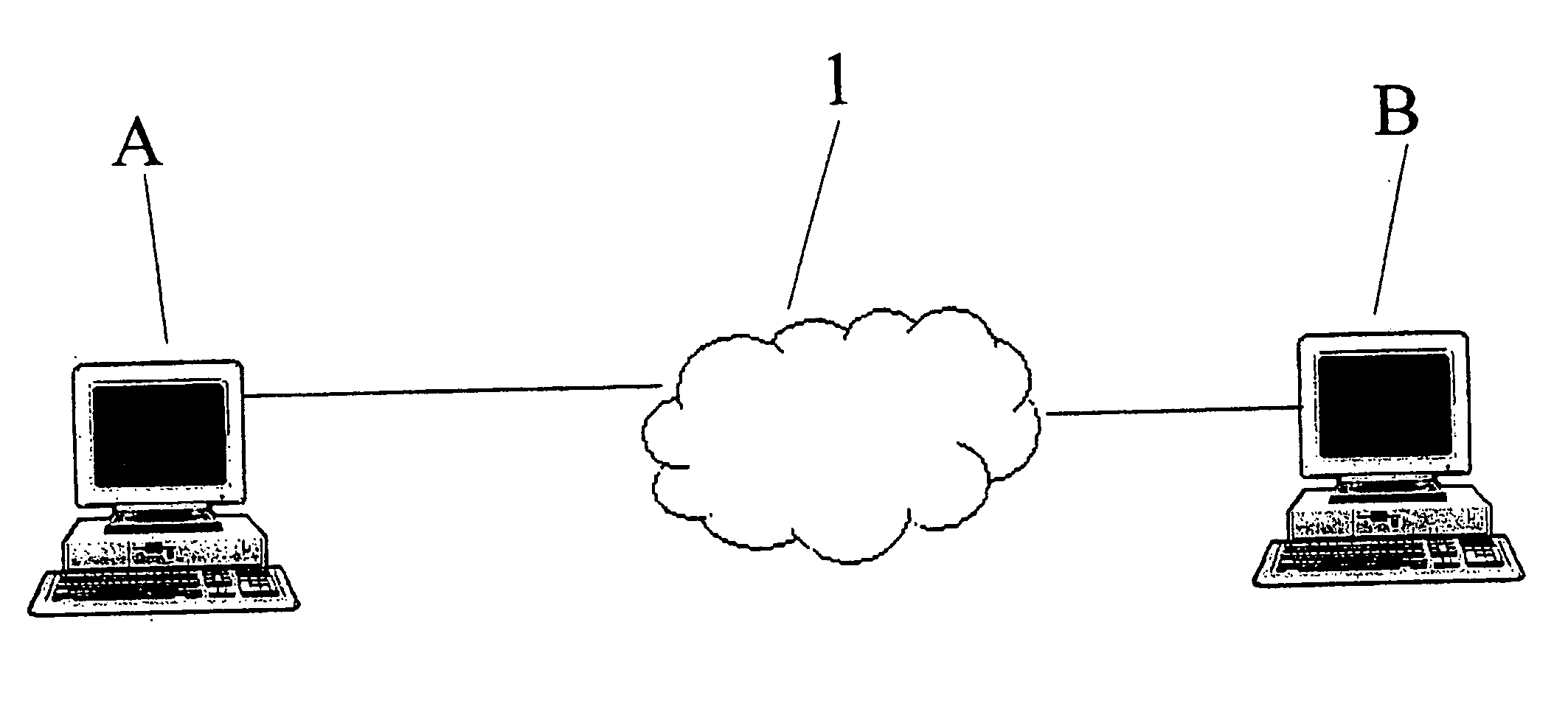
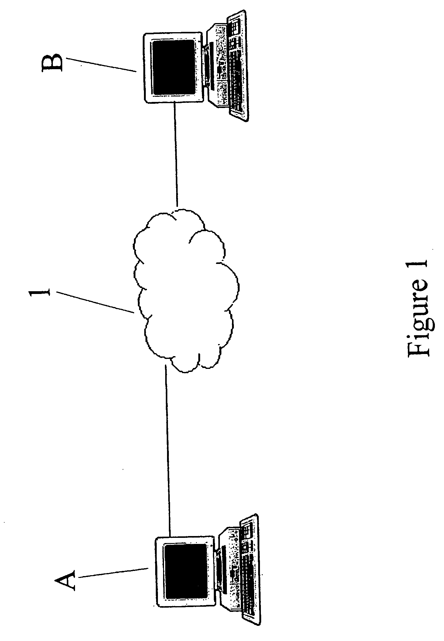
[0015] Referring to FIG. 1 of the accompanying drawings there is illustrated a communications network 1 comprising a first terminal A and a second terminal B. In this embodiment of the invention, the first terminal A and the second terminal B are both PCs and the communications network 1 is an IP based network, for example a corporate Local Area Network (LAN).

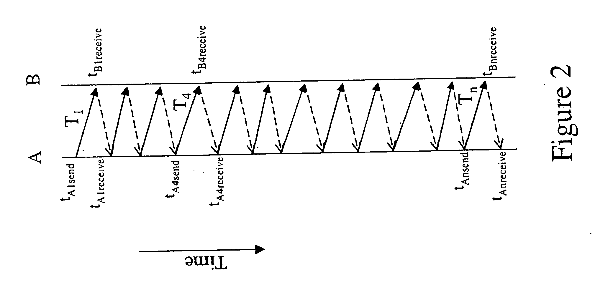
[0016] The first terminal A and the second terminal B each comprises an internal hardware clock (not shown). The internal clocks of the first terminal A and the second terminal B are not synchronised and thus at a given time, a synchronisation or timing offset δ exists between the two clocks. The timing offset δ may be defined as:

δ=TB−TA  (1)

[0017] where TA is the time indicated by the clock of the first terminal A and simultaneously, TB is the time indicated by the clock of second terminal B.

[0018] Whilst independently running clocks of PCs such as the first terminal A and second terminal B can be expected to keep reasonab...


PUM


Abstract

A system for determining a timing offset between a first clock and a second clock at respective first and second points in a communications network. A series of request signals is transmitted from the first point in the network to the second point in the network. A series of reply signals is transmitted from the second point in the network to the first point in the network. Each reply signal and a corresponding reply signal having a minimum round trip delay time are identified and a minimum single leg delay time is determined from the minimum round trip delay time. A timing offset between the clock values of the first clock and the second clock at a first instance is estimated, the estimation being based upon the minimum single leg delay time, and a transmission time and a reception time of one of the identified request signal and the corresponding reply signal, as given by the respective clocks at the transmission and reception points of the signal.

Description

BACKGROUND [0001] 1. Field of Invention [0002] This invention relates to a method of determining a timing offset between a first clock and a second clock in a communications network. [0003] 2. Background of the Invention [0004] It is standard for a device connected to a computer network to have an internal clock for time keeping purposes. Typical hardware clocks provide millisecond resolution and timing. Usually, the internal clocks of two or more devices communicating over a network run independently of each other and thus may not be synchronised. For certain types of network communication, it is desirable that the timing offset between the unsynchronised internal clocks of the two or more communicating devices be known or be predictable. For example, measuring network delay in an IP network is simplified if the timing offset between the clocks of the communicating devices is known. [0005] Network delay in an IP network is a measure of how long it takes for a packet to get from one...

Claims


Application Information

Patent Timeline
Patent Type & Authority Applications(United States)
IPC IPC(8): G04C13/00G04C11/00H04J3/06
CPCH04J3/0667
Inventor SMITH, JAMES DAVID
Owner UNIFY GMBH & CO KG
Why Eureka
Try Eureka