Optical transmission system and synchronization method using time reference pulse

a technology of optical transmission system and time reference pulse, which is applied in the direction of multi-channel communication, wavelength-division multiplex system, star/tree network, etc., can solve the problem of difficult to obtain rapid time-synchronization, and achieve the effect of rapid and accurate time-synchronization

Inactive Publication Date: 2012-02-28
KDDI CORP
View PDF10 Cites 4 Cited by
  • Summary
  • Abstract
  • Description
  • Claims
  • Application Information

AI Technical Summary

Benefits of technology

[0012]It is therefore an object of the present invention to provide an optical transmission system and a synchronization method using a time reference pulse, whereby it is possible to establish rapid and accurate time-synchronization even when a TDMA scheme is adopted in the transmission.
[0014]A time reference pulse that is synchronized with a time reference pulse applied to the optical terminal unit in network side can be generated at each of the optical terminal units in user side, by using a simple circuit structure, and it is possible to establish rapid and accurate time-synchronization.
[0018]A time reference pulse that is synchronized with a time reference pulse applied to the optical terminal unit in network side can be generated at each of the optical terminal units in user side, by using a simple circuit structure, and it is possible to establish rapid and accurate time-synchronization.
[0022]A time reference pulse that is synchronized with a time reference pulse applied to the optical terminal unit in network side can be generated at each of the optical terminal units in user side, by using a simple circuit structure, and it is possible to establish rapid and accurate time-synchronization.
[0026]A time reference pulse that is synchronized with a time reference pulse applied to the optical terminal unit in network side can be generated at each of the optical terminal units in user side, by using a simple circuit structure, and it is possible to establish rapid and accurate time-synchronization.

Problems solved by technology

This causes that the delayed amount cannot be fixed and therefore it is difficult to rapidly obtain time-synchronization.

Method used


Image

  • Optical transmission system and synchronization method using time reference pulse
  • Optical transmission system and synchronization method using time reference pulse
  • Optical transmission system and synchronization method using time reference pulse

Examples


Embodiment Construction

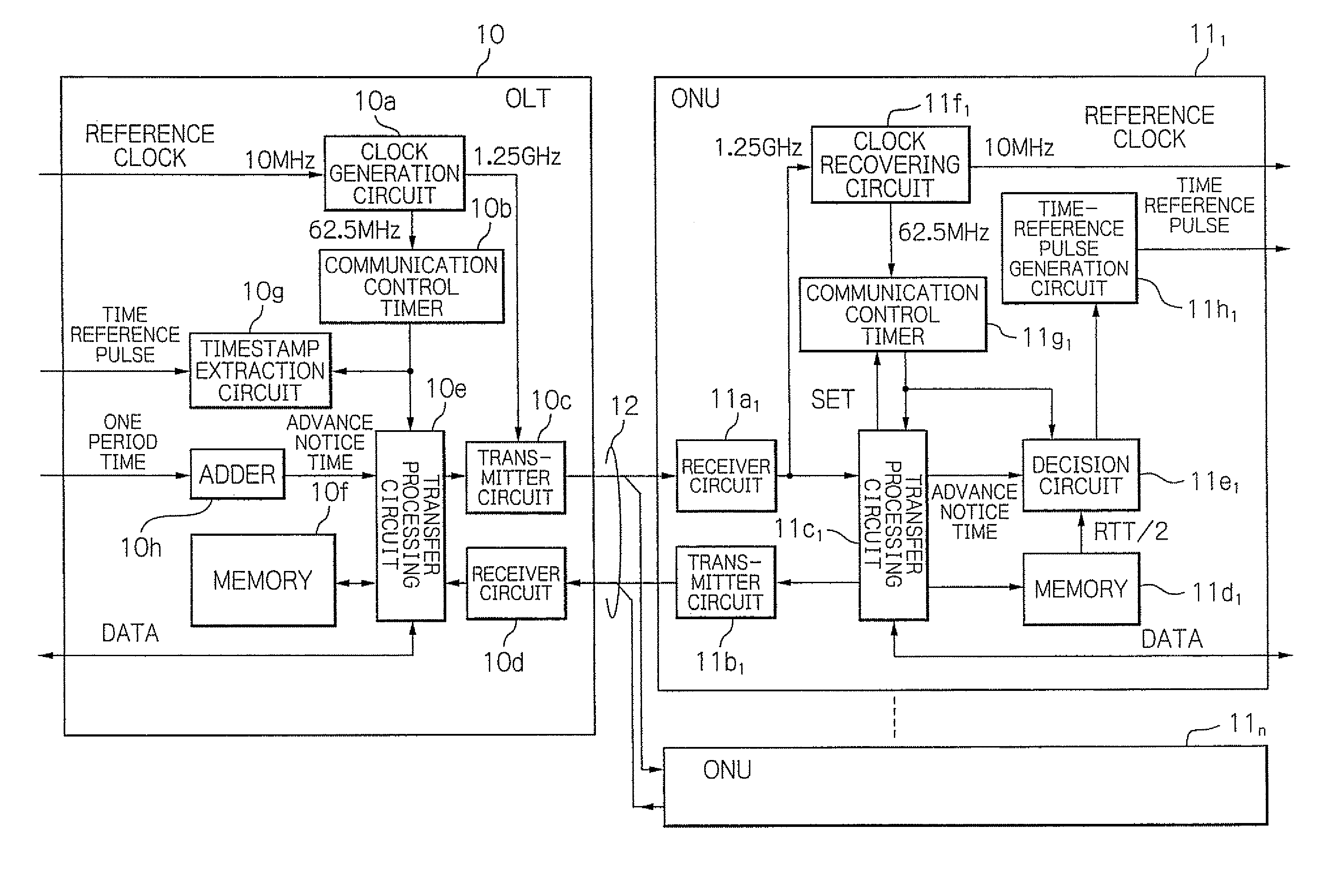
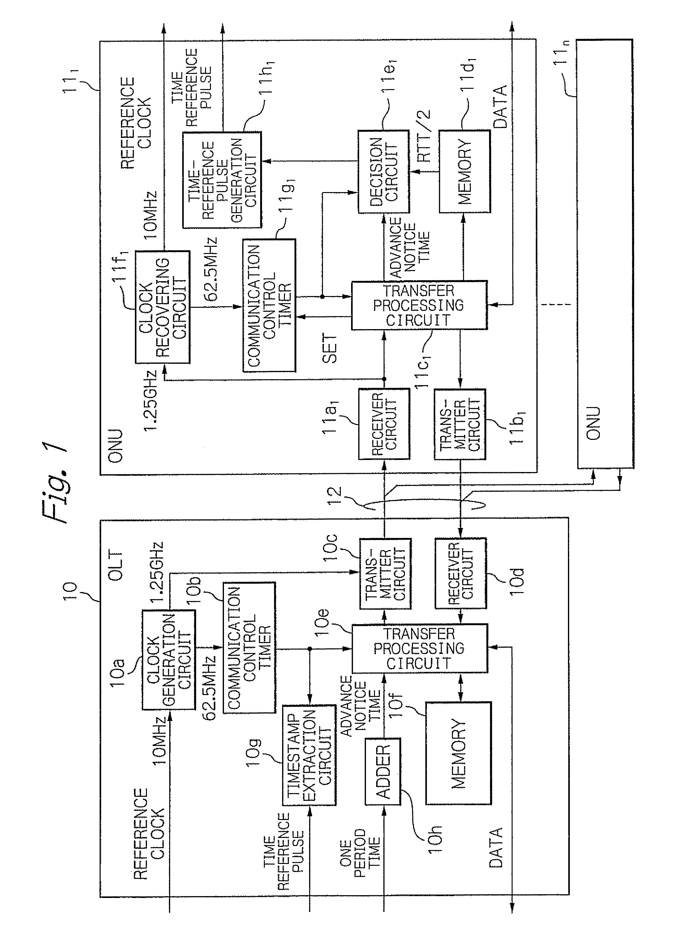
[0046]FIG. 1 schematically illustrates a configuration of a PON system as an embodiment of an optical transmission system according to the present invention.

[0047]As shown in the figure, the PON system in this embodiment has basically an OLT 10, a plurality of ONUs 111-11n (n is an integer of two or more) assigned to a plurality of users, and an optical transmission line 12 for connecting the OLT 10 and the ONUs 111-11n.

[0048]The optical transmission line 12 has at least one optical coupler (not shown) for coupling or branching signal light(s) at its intermediate point and is configured by a passive coupling device in general. Typically, one optical fiber is used for the optical transmission line 12 by performing wavelength divisional multiplexing for down and up transmissions. However, for easy understanding, the optical transmission line 12 is represented by two transmission lines of downlink and uplink in the figure.

[0049]The OLT 10 has a clock generation circuit 10a for generati...


PUM


Abstract

An OLT includes a first transmitter and receiver unit for transmitting and receiving signals with ONUs, a first communication control timer, a measurement unit for measuring a round trip time (RTT) between the OLT and each of ONUs, an advance notice time generation unit for generating an advance notice time signal by adding a predetermined time to a time information that indicates a time in the first communication control timer in response to a first time reference pulse, and a unit for controlling the first transmitter and receiver unit to transmit the generated advance notice time signal to each of the ONUs, and to transmit signals indicating measured RTT / 2 to the respective ones of the ONUs.

Description

PRIORITY CLAIM[0001]This application claims priority from Japanese patent application No. 2008-141858, filed on May 30, 2008, which is incorporated herein by reference.BACKGROUND OF THE INVENTION[0002]1. Field of the Invention[0003]The present invention relates to an optical transmission system and to a synchronization method using a time reference pulse. More concretely, the present invention relates to an optical transmission system with an optical terminal unit in network side and a plurality of optical terminal units in user side, in which the optical terminal unit in network side controls up-signals from the optical terminal units in user side in Time Division Multiplexing Access (TDMA) manner, and to the synchronization method using a time reference pulse.[0004]2. Description of the Related Art[0005]As for an optical transmission system in which an optical terminal unit in network side controls up-signals from optical terminal units in user side in TDMA manner, a Passive Optic...

Claims


Application Information

Patent Timeline
Patent Type & Authority Patents(United States)
IPC IPC(8): H04J14/08H04B10/07H04B10/27H04B10/272H04B10/524H04B10/54H04J14/00H04J14/02H04L7/00H04L12/44
CPCH04J3/0682H04Q11/0067H04J3/12H04Q2011/0079
Inventor HORIUCHI, YUKIO
Owner KDDI CORP
Why Eureka
Try Eureka