
Method and apparatus for round trip delay measurement in a bi-directional, point-to-point, serial data channel

a serial data channel and delay measurement technology, applied in the field of data transmission, can solve the problem of consuming valuable bandwidth in the communications system from unwanted recycling

Inactive Publication Date: 2007-10-23
BROCADE COMMUNICATIONS SYSTEMS
View PDF5 Cites 2 Cited by
  • Summary
  • Abstract
  • Description
  • Claims
  • Application Information

AI Technical Summary

Benefits of technology

"The patent text describes a method for measuring the delay in transmitting data between two switches in a Fibre Channel network. Before the measurement is started, the originating switch sends the value of a specific timing signal to the remote switch. The remote switch stores this value in a register and only sends back a matching signal to the originating switch when the echo function is enabled. This allows for more efficient measurement of the delay between the two switches."

Problems solved by technology

One disadvantage of this prior art method is that in order for the link round trip measurement to be performed, each switch must retransmit any TPS that it did not originate.
Such unwanted recycling consumes valuable bandwidth in the communications system.

Method used


Image

  • Method and apparatus for round trip delay measurement in a bi-directional, point-to-point, serial data channel
  • Method and apparatus for round trip delay measurement in a bi-directional, point-to-point, serial data channel
  • Method and apparatus for round trip delay measurement in a bi-directional, point-to-point, serial data channel

Examples


Embodiment Construction

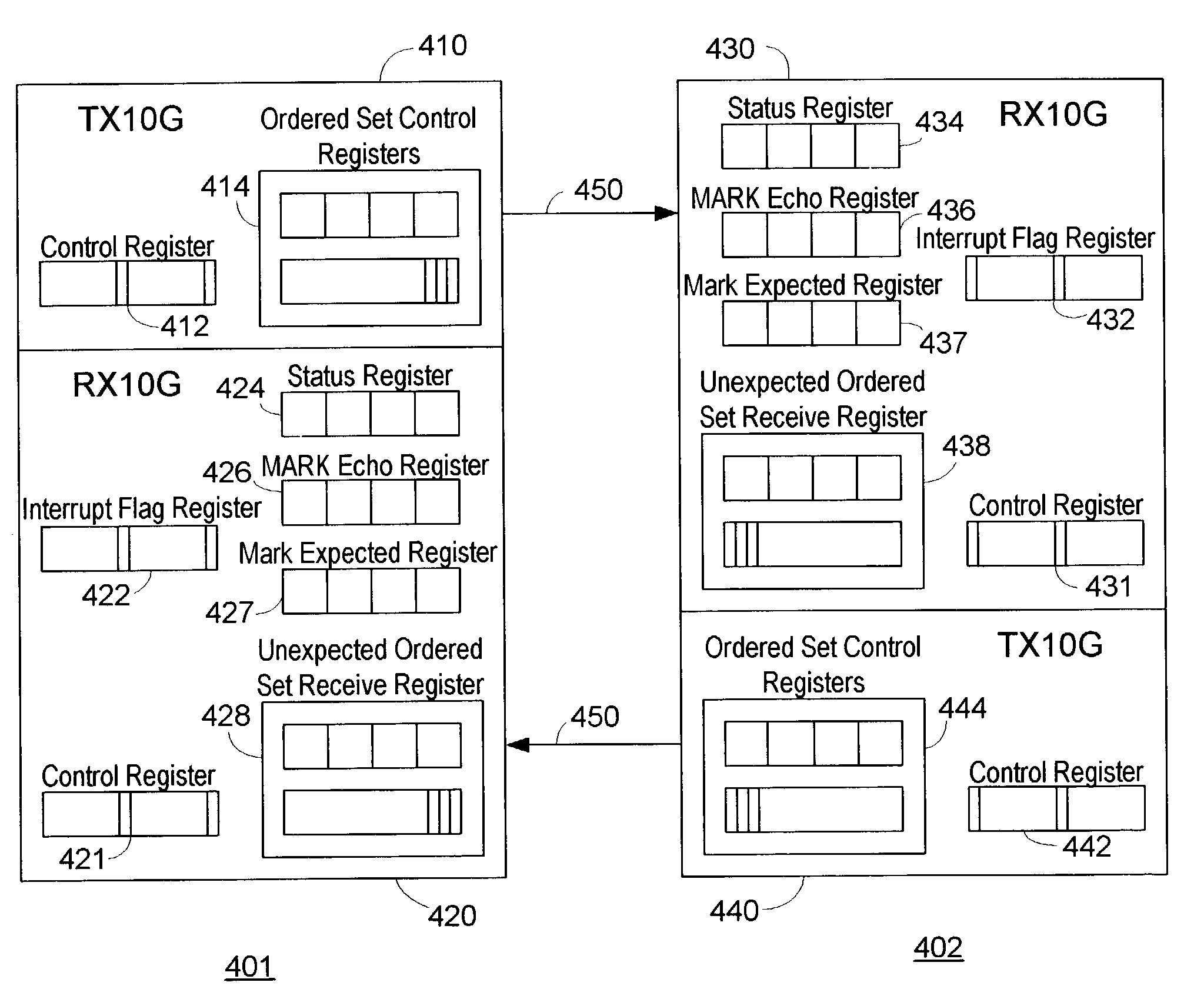
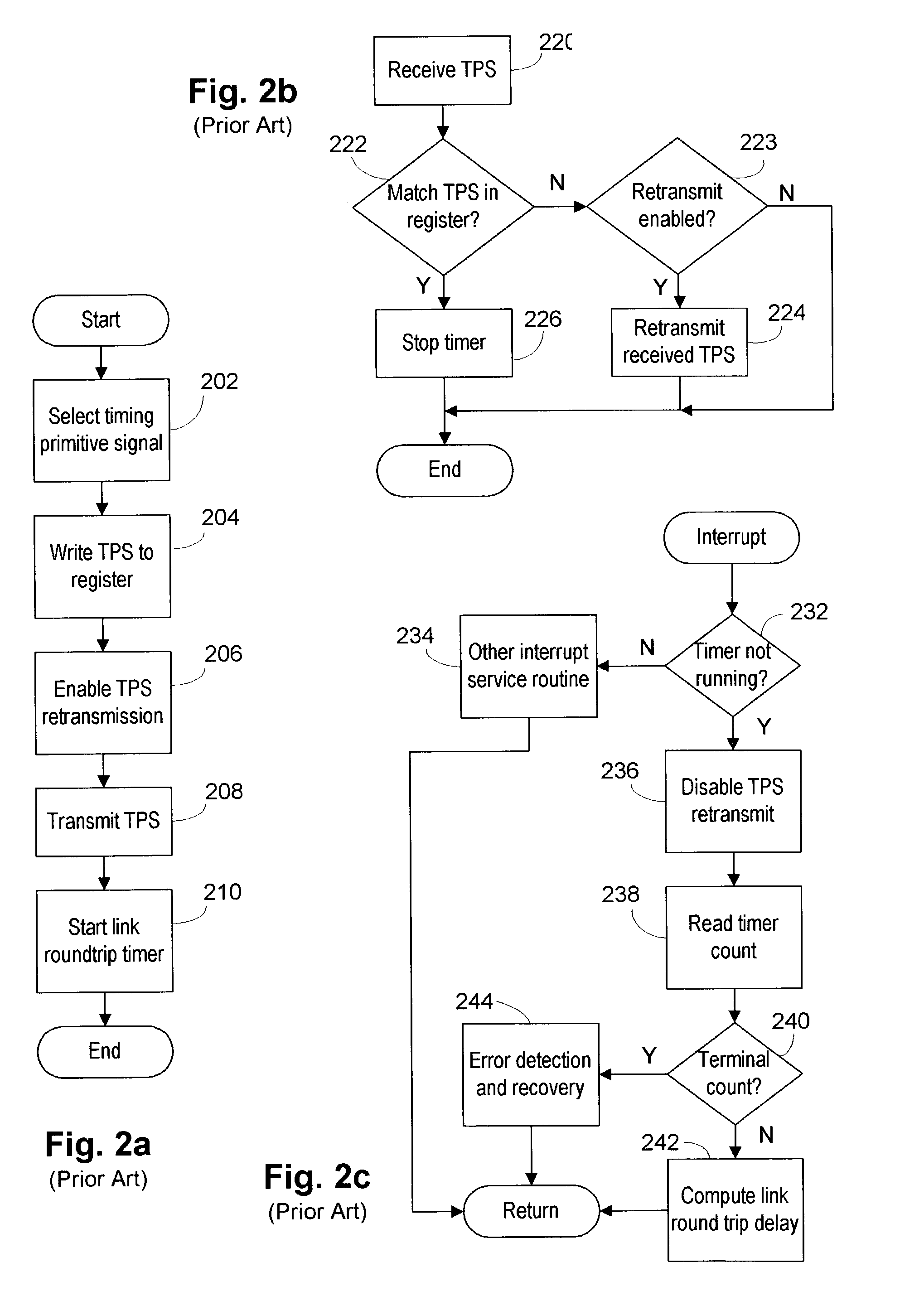
[0020]One example of a process which embodies the present invention is shown in flow chart form in FIGS. 3a, 3b and 3c. In Block 302 of FIG. 3a, a unique timing primitive signal may be selected by the originating switch (“Switch 1”). This particular timing primitive signal is then written to the control register of Switch 1 [Block 304] and the “expected register” of Switch 1 [Block 306]. The originating switch may send the value of the selected timing primitive signal to the responding switch (“Switch 2”) at the other end of the link [Block 308]. The timing signal primitive value may be contained in the payload of a frame sent by Switch 1 to Switch 2. A frame is a data unit containing a start-of-frame (SOF) delimiter, a header, the payload, a cyclic redundancy check value (for error detection and correction) and an end-of-frame (EOF) delimiter.

[0021]In one particular embodiment, Switch 2 stores the value of the timing primitive signal in an “echo register” within Switch 2 [Block 310...


PUM


Abstract

The link round trip delay between two switches in a Fibre Channel network may be determined by sending a particular timing signal value from an originating switch to a responding switch. The responding switch may store the timing signal value in an “echo” register for comparison to subsequently received timing signals. The originating switch may then send the pre-selected timing signal to the responding switch while simultaneously starting a timer. When the responding switch receives the timing signal, it may compare the value of the received signal to that stored in its echo register. If the value, is the same, the responding switch may retransmit—i.e., echo—the timing signal to the originating switch. When the originating switch receives the echoed timing signal, it may stop its timer and compute the link round trip delay time. The computed link round trip delay time between the originating switch and the responding switch may be advantageously used in fabric routing algorithms.

Description

BACKGROUND OF THE INVENTION[0001]1. Field of the Invention[0002]The invention relates generally to data transmission in a Fibre Channel network and more particularly, but not by way of limitation, to techniques for measuring the time required to send data over a particular high-speed link.[0003]2. Description of the Related Art[0004]As used herein, the term “Fibre Channel” refers to the Fibre Channel family of standards promulgated by the American National Standards Institute as ANSI X.3 / T11. In general, Fibre Channel defines a high-speed serial transport system that uses a hierarchically structured information exchange protocol consisting of frames, sequences and exchanges. A “frame” is the atomic unit of data transmission between two communicating devices. A “sequence” is a set of one or more related data frames transmitted unidirectionally from one device to another device within an exchange. An “exchange” is the basic construct for coordinating the transfer of information betwee...

Claims


Application Information

Patent Timeline
Patent Type & Authority Patents(United States)
IPC IPC(8): H04L12/28H04L12/56H04L12/24
CPCH04L43/0864H04L49/357H04L49/351H04L49/55
Inventor YAZDY, FARID A.MARTIN, KREG A.
Owner BROCADE COMMUNICATIONS SYSTEMS
Learn More