Push-to-X over cellular coordinated floor and packet scheduling

a technology of coordinated floor, which is applied in the field of push-to-x (ptx) service in a cellular telephone communication system, can solve problems such as time delay and waste of network capacity

Inactive Publication Date: 2006-06-15
MOTOROLA INC +1
View PDF16 Cites 44 Cited by
  • Summary
  • Abstract
  • Description
  • Claims
  • Application Information

AI Technical Summary

Problems solved by technology

There is a time delay, however, between the moment that a user initiates PTT service (usually indicated by pressing a PTT switch) and the moment a PTT connection is set up (usually indicated by a “ready” tone).
During this time delay, the originating user's mobile device usually has been assigned packet data slots for a data connection to the communication infrastr

Method used


Image

  • Push-to-X over cellular coordinated floor and packet scheduling
  • Push-to-X over cellular coordinated floor and packet scheduling
  • Push-to-X over cellular coordinated floor and packet scheduling

Examples


first embodiment

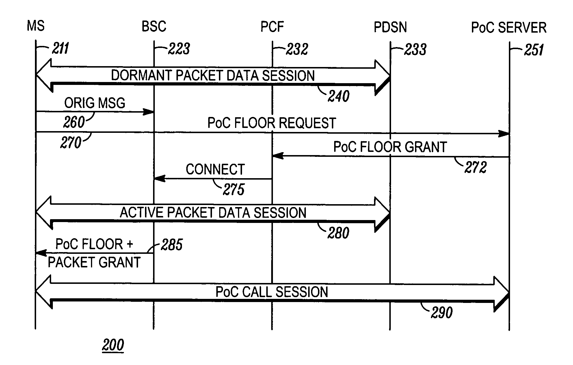
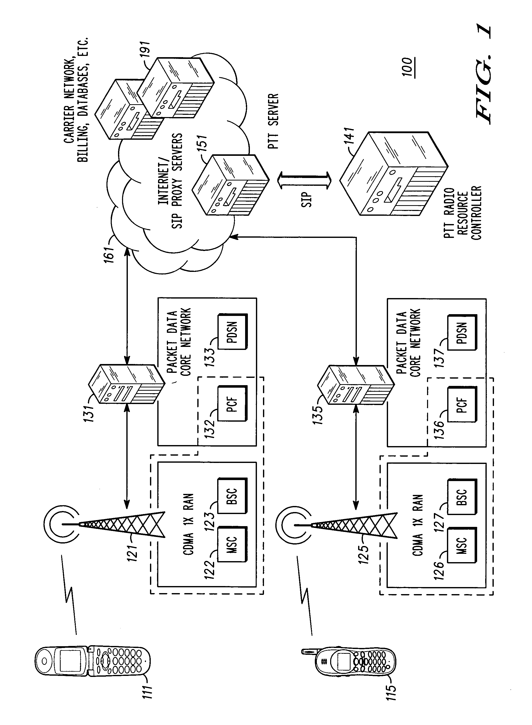
[0019]FIG. 2 shows a sample signal flow diagram 200 for setting up a push-to-talk call over the Third Generation (3G) Code Division Multiple Access (CDMA 1×) system 100 shown in FIG. 1 according to a Vertical line 211 represents signaling to and from an originating communication device (MS), such as communication device 111 shown in FIG. 1. Vertical line 223 represents signaling to and from a base station controller (BSC), which can be implemented as a component of a radio access network such as the CDMA 1× radio access network 121 shown in FIG. 1. Vertical line 232 represents signaling to and from a packet control function (PCF), which can be implemented as a component of a radio access network, such as the RAN 121 shown in FIG. 1. Vertical line 233 represents signaling to and from a packet data serving network (PDSN), which can be implemented as a component of a packet data core network, such as the packet data core network 131 shown in FIG. 1. Vertical line 251 represents signal...

second embodiment

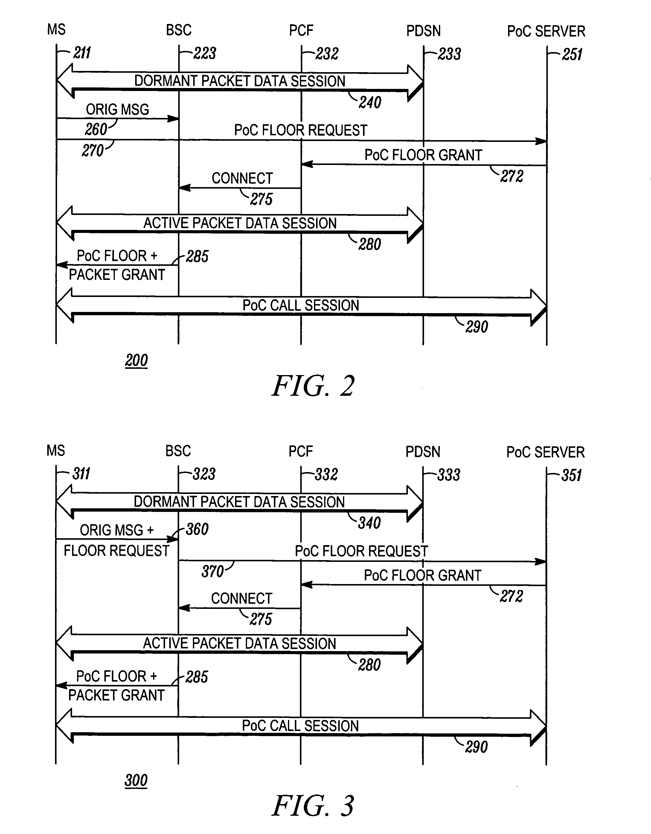
[0030] The remaining signal flows of FIG. 3 have reference numbers that are identical to those in FIG. 2 and represent similar messages and sessions previously described with reference to FIG. 2. If a called PoC communication device desires to participate, the user presses a PTX switch, which triggers a PoC floor request such as message 270 shown in FIG. 2. At this point, the PoC floor request is generally in the form of a RTCP message that is transported using an origination message or a short data burst at the radio layer. (Using a SIP message as a PoC floor request is inappropriate in this situation, because the call session has already been set up.) The signal flow for the new originating communication device continues as previously described in FIG. 2. As in FIG. 2, the second embodiment delays the active packet data session until after a PoC floor is granted by the PoC server 351. An additional savings in uplink packet data capacity occurs when the two messages 260, 270 of FIG...

third embodiment

[0035] Due to the layered structure of a message in this system, a BSC 523 cannot easily determine whether a message is a PoC floor control message or whether a PoC floor control message is specifically a PoC floor grant message. In other words, a BSC is not geared to inspect the area of a message that indicates that the message is a PoC floor control message or more specifically a PoC floor grant message. In this third embodiment, the traffic flow template message 545 instructs the PDSN 533 to inspect incoming PoC floor control messages for a value representing a PoC floor grant and then to modify the PoC floor control messages that contain a PoC floor grant so that the PCF 532 and BSC 523 can more easily identify that a message as a PoC floor grant message. In other words, modify the Generic Routing Encapsulation (GRE) header or payload to indicate a PoC floor grant.

[0036] When a user presses a PTT switch to request service for a PoC call, a PoC origination message 560 is sent fro...


PUM


Abstract

This coordinated floor and packet scheduling for Push-to-X over Cellular (PoC) services delays a packet data slot assignment until after a PoC floor has been granted (272) by a PoC server (251). By reducing the time period between slot assignment and floor grant, this method reduces the wasting of packet data network resources while the communication device (211) is waiting for a PoC floor grant. Setting up a Push-to-X over Cellular (PoC) call session includes an originating communication device (211) transmitting a PoC floor request message (270) to a PoC server (251), the PoC server (251) sending a PoC floor grant message (272) with treatment type “floor grant” to a packet control function, (232), the packet control function (232) assigning packet data slots to the originating communication device and setting up an active packet data session (280), and communicating a PoC floor grant and packet data slot assignment message (285) to the originating communication device (211).

Description

FIELD OF THE DISCLOSURE [0001] This disclosure relates generally to push-to-X (PTX) service in a cellular telephone communication system, and more particularly to reducing wasted network capacity in certain PTX over Cellular (PoC) connection set-ups. BACKGROUND OF THE DISCLOSURE [0002] Push-to-talk (PTT) refers to a half-duplex mode of communication during which a single user has mutually exclusive use of a communication channel for the transmission of voice information to another user or group of users. From an operational viewpoint, an originating party presses a PTT switch on a mobile device, possibly awaits a “ready” tone, speaks into a microphone of the mobile device, and then releases the PTT switch. At this point, a former called party can press a PTT switch on his own mobile device, possibly await a “ready” tone, speak into the microphone, and release the PTT switch. This procedure is repeated with different parties becoming the originating user and transmitting to one or mo...

Claims


Application Information

Patent Timeline
IPC IPC(8): H04L12/56
CPCH04W72/005H04W76/005H04W84/042H04L65/4061H04L65/4038H04W76/45H04W72/30H04W72/12
Inventor ALBERTH, WILLIAM P. JR.BALASURIYA, SENAKABI, HAONARASIMHA, MURALI
Owner MOTOROLA INC
Why Eureka
Try Eureka