
Method and station for transmitting data in a radio communication system

Inactive Publication Date: 2006-06-15
NOKIA SIEMENS NETWORKS GMBH & CO KG
View PDF7 Cites 10 Cited by
  • Summary
  • Abstract
  • Description
  • Claims
  • Application Information

AI Technical Summary

Benefits of technology

[0012] An object of the invention is thus to specify an advantageous method or transmitter and / or receiver stations in radio communication networks, in particular in ad hoc networks, which reduce collisions on the radio medium caused by moving stations or moving interference sources.
[0016] It is particularly advantageous to determine or to estimate an expected change, especially a decrease in the intensity of the transmission signal at the first receiving station dependent on an actual and / or maximum possible relative velocity of the first transmitting station and of the first receiving station to each other. Such a relative velocity between the first transmitting station and the first receiving station makes it possible to estimate whether a change is to be expected in the receiving intensity of the desired receive signal in the first receiving station, which, in the end, allows a higher or lower intensity in an interference signals that is to be expected or possibly to be expected.
[0018] It is advantageous to use standard maximum possible or maximum reasonable velocity for the stations and interference sources within a detection area of the first receiving station without the related velocity information and / or for the stations and interference sources outside a detection area of the first receiving station without the related velocity information. In this way, in the event that there is no information on the interference sources or other stations, a standard value, or, where receiving conditions are to be kept specially high, a worst possible value, can be used for the velocities of the stations and / or possible interference sources, so that even where there are no corresponding options for determining or receiving options for identifying velocities and / or interference signals, there is the possibility of applying the method.

Problems solved by technology

If the power used when transmitting is too great, or if an outside station transmitting on the same resource moves into the receiving area of a receiving station, this results in increased interference on various connections and in a reduction in the quality of reception in the individual connections.
What is problematic, especially with ad hoc networks, is a situation where two clusters each having one transmitting and one receiving station are moving towards each other.
In particular with clusters that are moving towards each other quickly, there is a danger that the receiving station of a clusters, as well as receive signals from its own assigned transmitting station, also receives signals from the other transmitting station of the other cluster.
In this case, interference would occur, which in a bad case could prevent a reconstruction of the desired receive signal.
Disadvantageously, the maximum permitted transmitting power and the possibilities for adapting the error correction capacity are limited and, therefore, not sufficiently suited to compensate when the mobility is high.
Moreover, the use of power control mechanisms can even increase system instability within mobile ad hoc networks.
Disadvantageously the power control mechanisms currently used are not sufficiently powerful for such compensation.

Method used


Image

  • Method and station for transmitting data in a radio communication system
  • Method and station for transmitting data in a radio communication system
  • Method and station for transmitting data in a radio communication system

Examples


Embodiment Construction

[0030] Reference will now be made in detail to the preferred embodiments of the present invention, examples of which are illustrated in the accompanying drawings, wherein like reference numerals refer to like elements throughout.

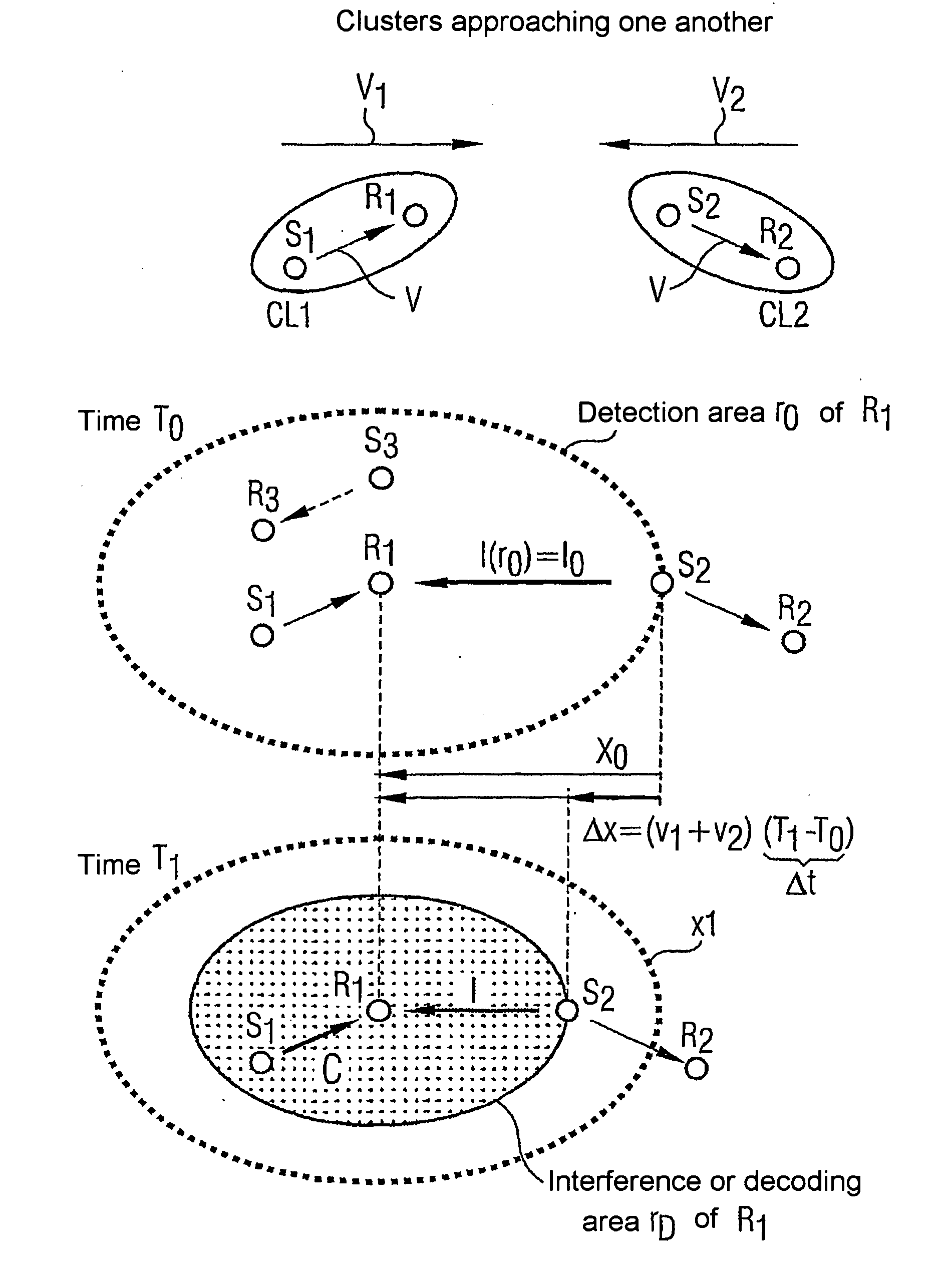
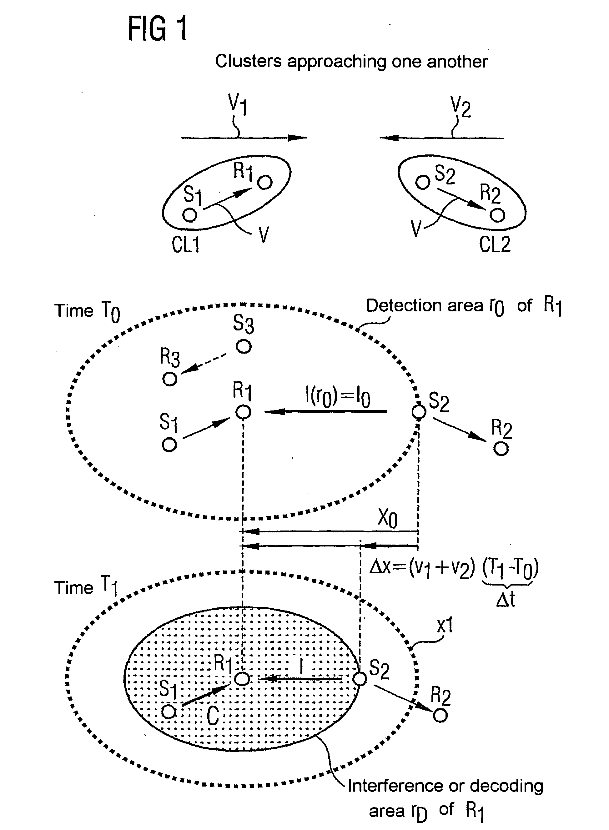
[0031] As can be seen from FIG. 1, clusters CL1, CL2—each made up of stations S1, R1, S3, R3 or S2, R2 communicating with each other via radio interfaces V—develop into so-called ad hoc radio networks as an example of a radio communication system. To simplify the following description, one station at a time S1 or S2 of the first or second cluster CL1, CL2 is regarded as the transmitting station S1 or S2 and a further station R1, R2 of the first or second cluster CL1, CL2 is regarded as the receiving station R1, R2. Of course, it is also possible and standard to transmit in the opposite direction. In the transmission illustrated, it is assumed that data with signaling and / or information content is transmitted by the respective transmitting station S1, S2 to ...


PUM


Abstract

In a communication system, a first transmitting station transmits a transmission signal to a first receiving station for transmitting a sequence of data via a radio interface. The radio interface is monitored with respect to an interference signal from an interference source prior to transmission via at least one of the first transmitting station and the first receiving station. The transmission only begins if the radio interface is sufficiently free from interference for a moment in time.

Description

CROSS REFERENCE TO RELATED APPLICATIONS [0001] This application is based on and hereby claims priority to European Application No. 02019237.3 filed on Aug. 27, 2002, the contents of which are hereby incorporated by reference.BACKGROUND OF THE INVENTION [0002] 1. Field of the Invention [0003] The invention relates to a method for transmitting data in a radio communication system or a mobile transmitter and / or receiver station for such purpose. [0004] 2. Description of the Related Art [0005] In mobile communication systems, such as, for example, GSM (Global System for Mobile Communications) or UMTS (Universal Mobile Telecommunications System), the transmitting power of the communication partner is optimized with respect to the quality of the connection. To this end, control mechanisms are used, which set the transmitting power so as to attain a desired bit error rate and / or a certain level of reception. [0006] In ad hoc networks, also referred to as self-organizing networks, several n...

Claims


Application Information

Patent Timeline
IPC IPC(8): H04B7/00H04Q7/00H04B7/26H04L1/00H04W24/00H04W74/08H04W84/12H04W84/18H04W88/02
CPCH04L1/0001H04L1/0007H04L1/0019
Inventor HALFMANN, RUDIGERLI, HUILOTT, MATTHIASSCHULZ, EGON
Owner NOKIA SIEMENS NETWORKS GMBH & CO KG
Features
  • Generate Ideas
  • Intellectual Property
  • Life Sciences
  • Materials
  • Tech Scout
  • Unparalleled Data Quality
  • Higher Quality Content
  • 60% Fewer Hallucinations
Learn More