Spinal stabilization device and methods

Active Publication Date: 2006-06-15
PIONEER SURGICAL TECH INC
View PDF46 Cites 101 Cited by
  • Summary
  • Abstract
  • Description
  • Claims
  • Application Information

AI Technical Summary

Problems solved by technology

Spinal damage, disease, or deformity are serious and often painful conditions that may become life-threatening conditions.
Some conditions impinge on the spine and lead to pain, such as disc degeneration or tumors.
If the spinal cord is damaged, either directly or by the inability of the damaged vertebrae to protect the spinal cord, the communication between the brain and organs or limbs may be lost, resulting in organ failure or paralysis.
Such conditions, if not properly managed, can lead to long-term pain, other complications, and ever-diminishing quality of life.
The vertebral fragments or damaged nucleus will likely impinge on the spinal cord, causing pain, numbness, or reduced motor capabilities in the limbs.
However, in the absence of proper medic

Method used


Image

  • Spinal stabilization device and methods
  • Spinal stabilization device and methods
  • Spinal stabilization device and methods

Examples


Embodiment Construction

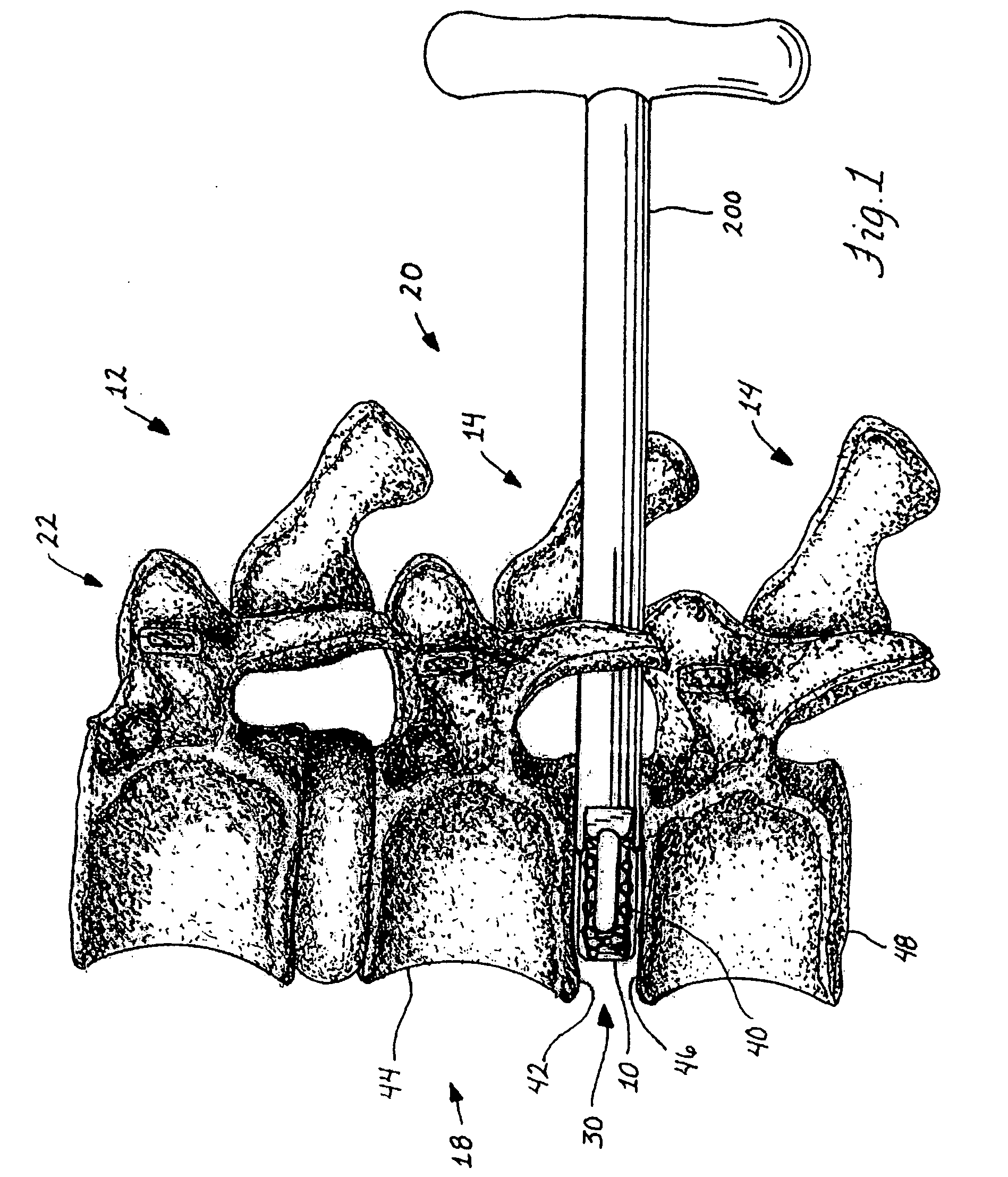
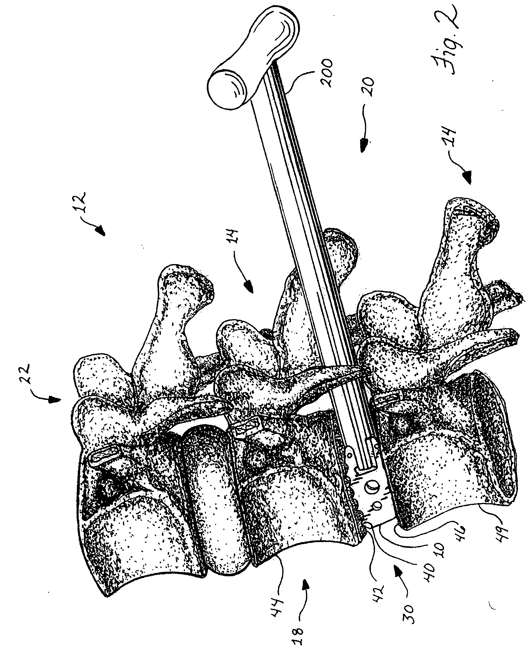
[0053] Referring initially to FIGS. 1 and 2, a vertebral body replacement device or implant 10 for spinal fusion surgery is represented as being inserted within a spinal column 12. The spinal column includes a series of vertebrae 14 and spinal discs 16 located between adjacent vertebrae 14. The spinal column 12 has an anterior side 18 and a posterior side 20 wherein the vertebrae 14 include a portion 22 on the posterior side 20 in which the spinal cord (not shown) is located.

[0054] In FIGS. 1 and 2, the implant 10 is shown being inserted from a posterior side 20 into an intervertebral space 30. Through the lumbar region of the spine 12, access to the intervertebral space 30 from the posterior side 20 avoids needing to go through the abdomen, which would require a general surgeon. In the cervical region (not shown) of the spine 12, it is preferred to access the spine 12 from the anterior side 18, principally due to the curvature of the cervical vertebrae. An implant 500 for use in t...


PUM


Abstract

Devices and methods for immobilizing adjacent vertebrae are disclosed including the utilization of one or more implants inserted between adjacent vertebrae and having protrusions thereon for substantially fixedly securing with the vertebrae. In one form, an implant may be inserted in a first orientation and then rotated to a second orientation having a larger profile. A second implant may also be inserted in the same vertebral space in the same manner. A trial spacer may be used to determine the proper implant size. In another form, an implant may be inserted already in the fusion orientation. The implants and trial spacer, as well as a spreader and/or a scraper for preparing the intervertebral space, may be inserted in the vertebral space with the same insertion tool. The inserter tool may include a threaded member for attachment with the implants or other devices.

Description

CROSS-REFERENCE TO RELATED APPLICATION(S) [0001] This application claims priority to U.S. Provisional Application Ser. No. 60 / 622,029, filed Oct. 26, 2004, and titled “Spinal Stabilization Device and Methods,” the entirety of which is incorporated herein by reference.FIELD OF THE INVENTION [0002] The invention relates to spinal stabilization devices and methods and, in particular, to devices for implantation in a vertebral space between adjacent vertebrae for immobilization and fusion of the vertebrae and methods for implantation of such devices and insertion of related components into the vertebral space. BACKGROUND OF THE INVENTION [0003] Spinal damage, disease, or deformity are serious and often painful conditions that may become life-threatening conditions. Some conditions impinge on the spine and lead to pain, such as disc degeneration or tumors. Others conditions involve abnormalities, such as scoliosis or spinal stenosis, where a person's spine is more susceptible to injury o...

Claims


Application Information

Patent Timeline
IPC IPC(8): A61F2/44A61F2/46A61B17/88
CPCA61B17/1604A61B17/1659A61B17/1671A61B2017/0256A61F2/4465A61F2/447A61F2/4611A61F2/4684A61F2002/3008A61F2002/30616A61F2002/30785A61F2002/30828A61F2002/30841A61F2002/4475A61F2002/4619A61F2002/4627A61F2002/4629A61F2250/0098A61F2002/30593Y10S606/914
Inventor PALTZER, ADAM
Owner PIONEER SURGICAL TECH INC
Why Eureka
Try Eureka