
System for diagnosing facility apparatus, managing apparatus and diagnostic apparatus

a technology for managing equipment and facilities, applied in the direction of testing/monitoring control systems, program control, instruments, etc., can solve the problems of limiting the only thing that can be done by the person in charge of managing the facility equipment, lacked objectivity in judgment results, and insufficient correctness of judgment results, so as to reduce the burden of information transfer on the communication network and improve the security of information

Inactive Publication Date: 2006-06-15
ASAHI KASEI ENG CORP +1
View PDF40 Cites 14 Cited by
  • Summary
  • Abstract
  • Description
  • Claims
  • Application Information

AI Technical Summary

Benefits of technology

[0013] As the facility management data analysis program is uploaded to the user side and the advanced analysis is performed again on the user side, only a small information amount solely on analysis results is sent to the facility diagnosis center side without necessity to send raw data of an enormous information amount such as the facility state detecting information detected by the facility state detecting means to the facility diagnosis center side, and so a burden of information transfer on the communication network is alleviated.
[0014] In addition, security of the information is improved because the raw data is not exchanged on the communication network.

Problems solved by technology

In the aforementioned example in the past, however, a judgment was made based on personal knowledge and experience to the extent that the person in charge of managing the facility apparatus can deal with it, so that the judgment result was not necessarily correct and there were the cases, according to circumstances, where a wrong judgment was made and the judgment result lacked objectivity.
However, it requires expertise in its own way to solve problems related to predictive maintenance such as facility diagnosis, predictive diagnosis and optimum operating conditions of the rotating apparatuses or a grasp of remaining life thereof, and so there is a limit to what can be done only by the person in charge of managing the facility apparatus.
Therefore, it is desirable to have the technically trained personnel with such expertise stationed in the plant, and yet it is difficult in many cases in consideration of the cost aspect of the plant operation such as the increased efficiency of the personnel.

Method used


Image

  • System for diagnosing facility apparatus, managing apparatus and diagnostic apparatus
  • System for diagnosing facility apparatus, managing apparatus and diagnostic apparatus
  • System for diagnosing facility apparatus, managing apparatus and diagnostic apparatus

Examples


Embodiment Construction

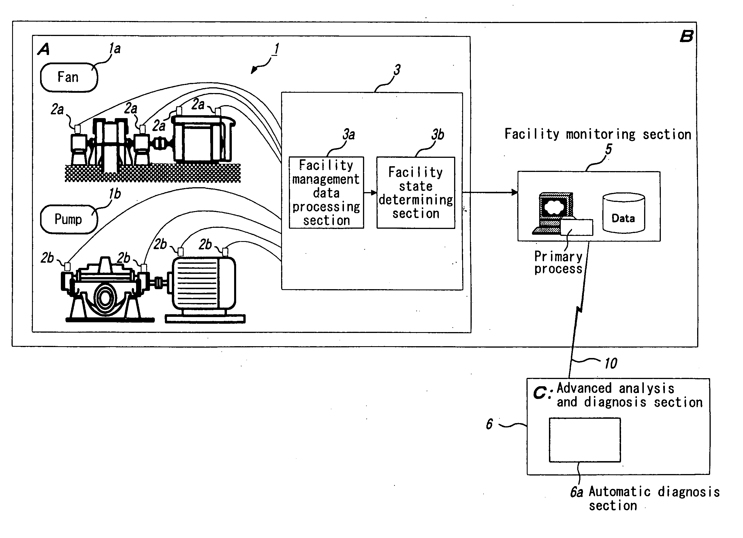
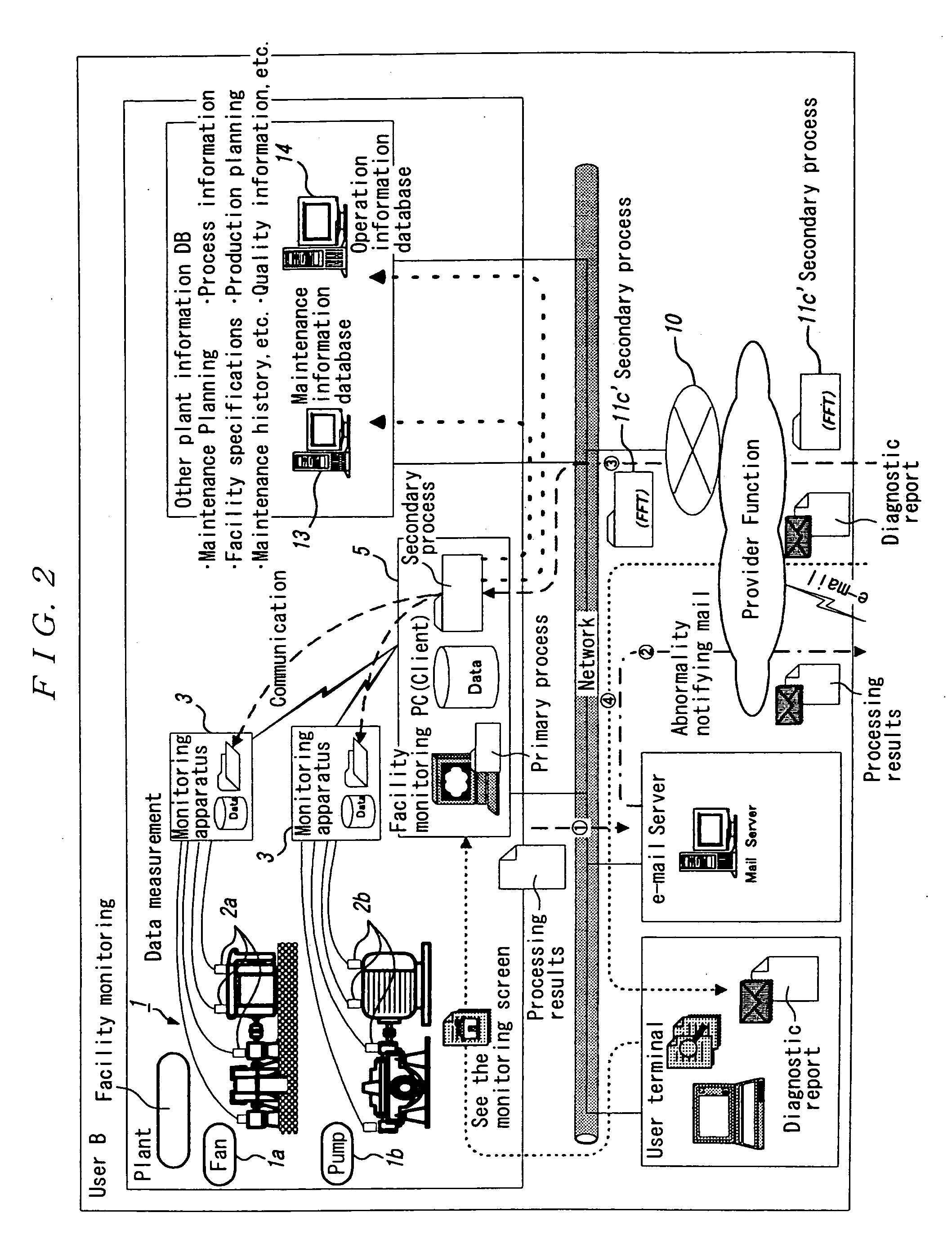
[0030] Next, an embodiment of a system for diagnosing a facility apparatus related to the present invention will be concretely described by using the drawings. FIG. 1 is a block diagram showing a configuration of the system for diagnosing the facility apparatus related to the present invention, FIG. 2 is a block diagram showing a user-side configuration of the system for diagnosing the facility apparatus related to the present invention, FIG. 3 is a diagram showing a configuration example of a communication network between a facility monitoring section and an advanced analysis and diagnosis section, FIG. 4 is a block diagram showing the configurations of facility state detecting means and the advanced analysis and diagnosis section, FIG. 5 is a block diagram showing the configuration of the advanced analysis and diagnosis section, FIG. 6 is a diagram showing a detailed configuration of an advanced data analysis section, and FIG. 7 is a diagram for explaining a relationship between a...


PUM


Abstract

The present invention relates to a system for managing and diagnosing a state of a facility apparatus, and an object thereof is to provide a system for diagnosing the facility apparatus wherein, if information falling under a level of abnormality is extracted from gathered information on an operating state of the facility apparatus, an advanced analysis and diagnosis section on a facility diagnosis center side performs an advanced analysis and diagnosis process and promptly notifies a user side of the information on the best way of dealing with the facility apparatus determined to be abnormal, and further uploads a facility management data analysis program from the advanced analysis and diagnosis section to a facility monitoring section on the user side so that raw information of a large information amount can be analyzed on the user side without sending it to the facility diagnosis center side. A facility management data processing section (3a) signal-processes facility state detecting information detected by facility state detectors (2a, 2b) mounted on a facility apparatus (1), a facility state determining section (4) determines a level of the signal-processed information comparing with a management reference value and outputs it, the facility monitoring section (5) gathers and processes the information related to the level-determined facility apparatus (1) and sends it to the advanced analysis and diagnosis section (6) via a communication network (10), and the advanced analysis and diagnosis section (6) performs an advanced analysis of the information and identifies a cause of the abnormality of the facility apparatus (1) concerned and improvement measures thereof to send the identified results to the facility monitoring section (5). In addition, it is characterized in that the facility management data analysis program is uploaded from the advanced analysis and diagnosis section (6) to the facility monitoring section (5) so that the advanced analysis can be performed on the user side B.

Description

TECHNICAL FIELD [0001] The present invention relates to a system for managing and diagnosing a state of a facility apparatus. BACKGROUND ART [0002] In the past, as for management of a facility apparatus of a plant and so on of a common enterprise, it was general that, while constantly watching operating situation of the facility apparatus, a person in charge of managing the facility apparatus further monitored a state of the facility apparatus at the site when an abnormality occurs as to vibration, sound, pressure, temperature and so on thereof, and stopped its operation, as the case may be, to investigate the cause and urgently repair it or replace a part, or to refer it to a facility apparatus manufacturer and consider countermeasures comparing with it when the situation further became serious. [0003] In the aforementioned example in the past, however, a judgment was made based on personal knowledge and experience to the extent that the person in charge of managing the facility ap...

Claims


Application Information

Patent Timeline
Patent Type & Authority Applications(United States)
IPC IPC(8): G06F11/00G05B23/02
CPCG05B2219/31205G05B2219/31434G05B2219/31448G05B23/0229G05B23/0272G05B23/0275
Inventor YOSHIE, OSAMUSATO, NOBUYOSHIFUKUNAGA, TATSUYA
Owner ASAHI KASEI ENG CORP
Learn More