Fuel system

Inactive Publication Date: 2006-06-22
GOODRICH CONTROL SYST LTD
View PDF7 Cites 22 Cited by
  • Summary
  • Abstract
  • Description
  • Claims
  • Application Information

AI Technical Summary

Benefits of technology

[0012] In accordance with the present invention there is provided a fuel control system for a staged combustion engine comprising a fuel metering unit including a fuel metering valve, a fuel staging unit receiving fuel from the metering valve of the fuel metering unit and incorporating a staging valve for dividing the flow of fuel from the fuel metering unit to pilot burner and main burner output lines, a connec

Problems solved by technology

Such an arrangement accommodates EECU or FMU failure resulting in excessive metering valve opening and shuts down the engine to prevent overthrust increasing to a dangerous extent.
During flight however the situation is somewhat more critical since an overthrust event in one engine of, for example, a twin engine aircraft could, if dealt with by engine shut-down, result in potentially dang

Method used


Image

  • Fuel system
  • Fuel system
  • Fuel system

Examples


Embodiment Construction

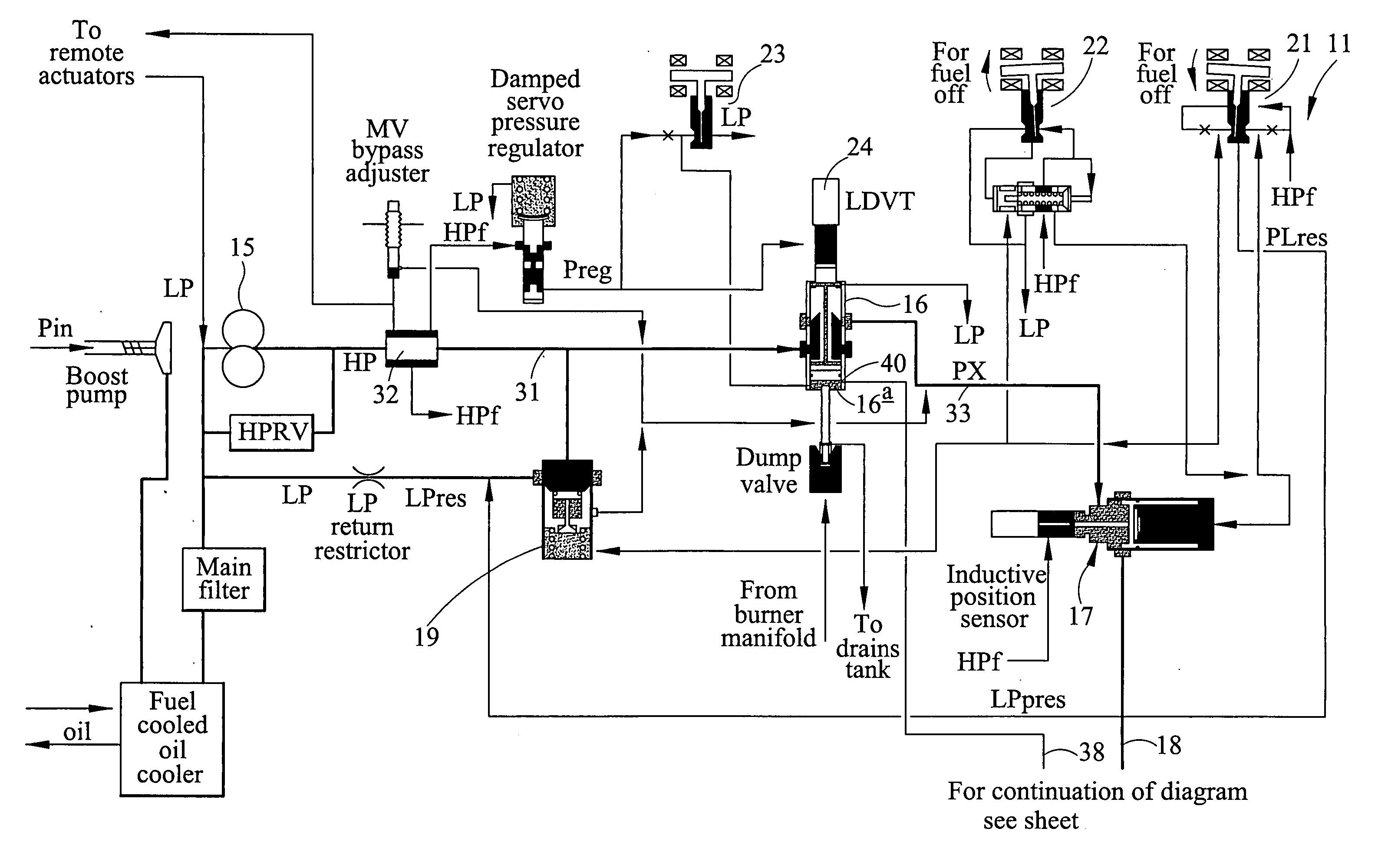
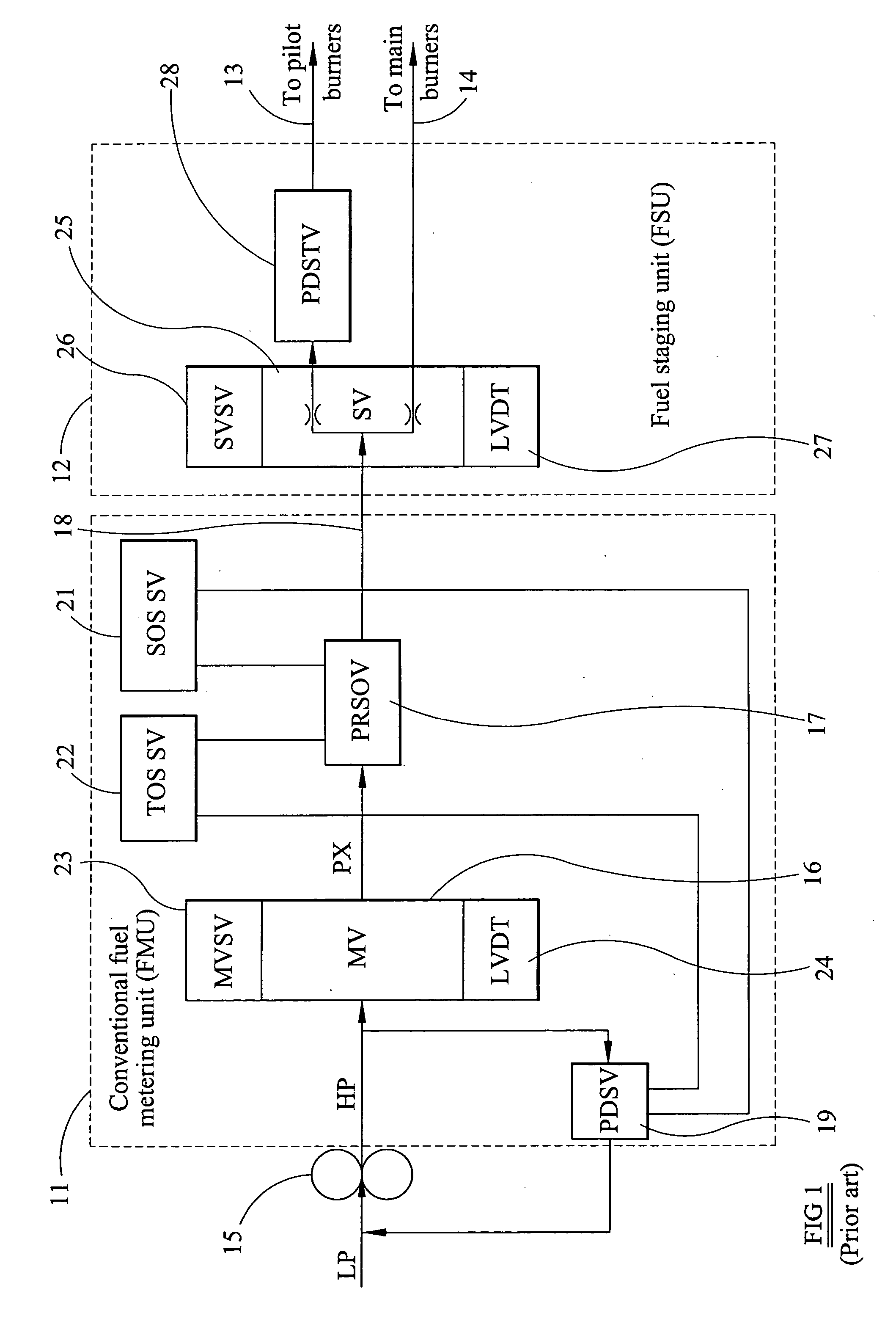
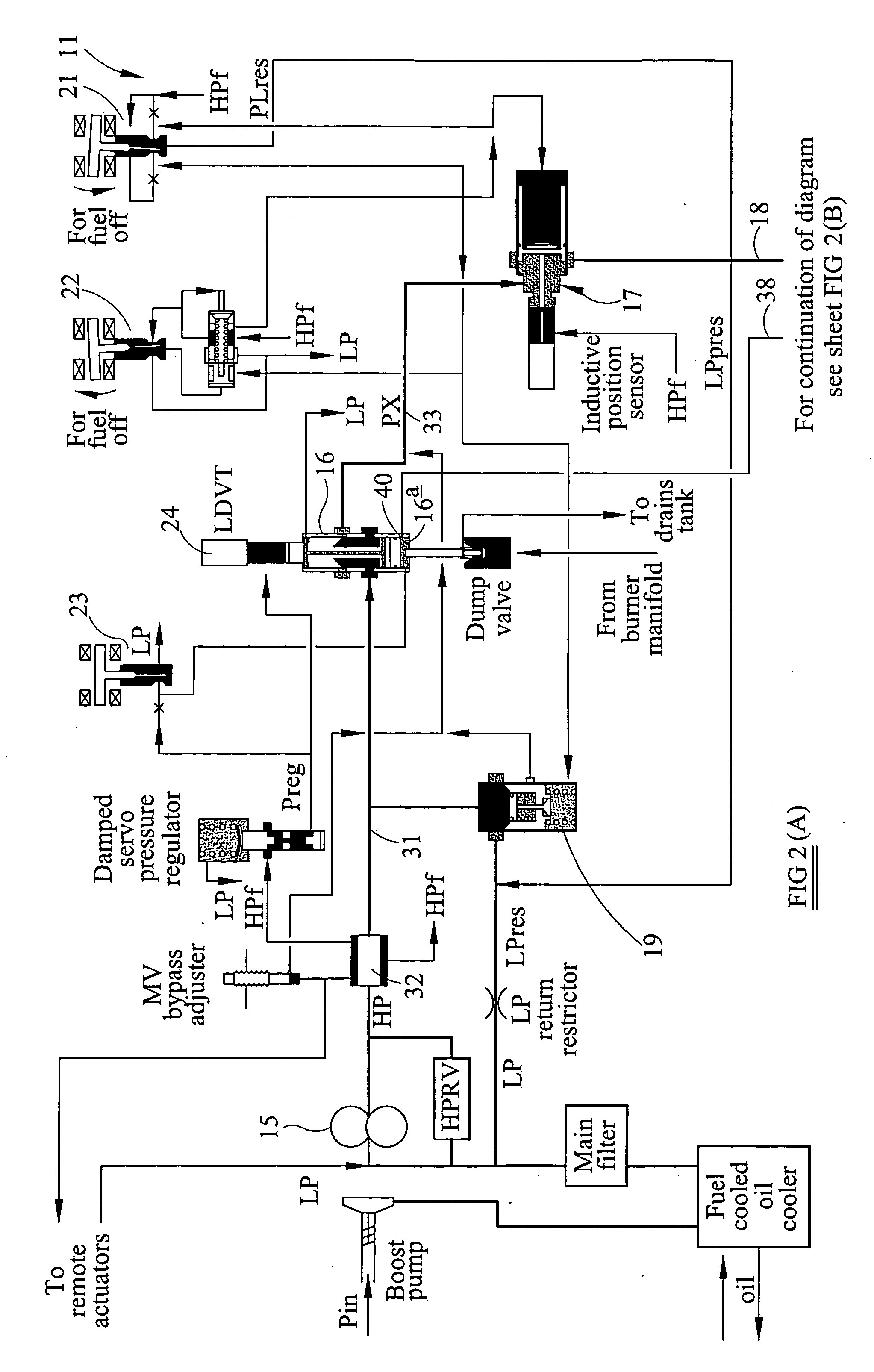
[0022] Referring first to FIG. 2 of the accompanying drawings the fuel system includes a fuel metering unit generally indicated at 11 (FIG. 2(A)), and a fuel staging unit shown in a solid line boundary and indicated by the reference numeral 12 (FIG. 2(B)). The fuel metering unit 11 is generally of conventional form and receives a supply of fuel at high pressure (HP) from a gear pump 15 driven from the main shaft of the associated gas turbine engine. The inlet of the pump 15 is supplied in conventional manner from a fuel reservoir by means of a boost pump or lift pump and the pressure at the inlet of the gear pump is defined as low pressure (LP) and which may be, in practice, above atmospheric pressure but substantially below HP. A supply line 31 from the outlet of the pump 15 contains a fuel filter 32 and provides an HP supply to the inlet gallery of a metering valve 16 and thus to the variable metering orifice of the valve 16. As is conventional in metering valves a spool of the va...


PUM


Abstract

A fuel control system for a staged combustion engine comprising, a fuel metering unit including a fuel metering valve having a fuel metering orifice the opening of which is varied to meter the flow of fuel through the metering valve in use, a fuel staging unit receiving fuel from the metering valve of the fuel metering unit and incorporating a staging valve for dividing the flow of fuel from the fuel metering unit to pilot burner and main burner output lines, a connection between a fuel pressure region of said fuel metering unit and a port of said staging valve, and, overthrust detection means causing said staging valve, in response to overthrust detection, to connect said port of said staging valve to low pressure, whereby to drain fuel under pressure from said pressure zone of said fuel metering unit to low pressure to limit or reduce the fuel supplied from the fuel metering unit to the fuel staging unit and thus to the engine in use.

Description

TECHNICAL FIELD [0001] This invention relates to a fuel supply system for a gas turbine engine of the kind having staged combustion, particularly, but not exclusively for use in a multi-engine aircraft application. BACKGROUND ART [0002] In a staged combustion gas turbine engine, burners of the engine are divided into at least two groups which can, for convenience, be referred to as pilot burners and main burners. It is to be understood that the main burner group may comprise a number of main burner sub-groups, but this distinction is not of importance to the invention. Generally, while an engine is operative, fuel is supplied continuously to the pilot burners, but is supplied to the main burners only while the thrust and / or emission requirements imposed upon the engine require that the main burners are operative in addition to the pilot burners. [0003] In the accompanying drawings FIG. 1 is a diagrammatic representation of a known arrangement of a fuel metering unit supplying metere...

Claims


Application Information

Patent Timeline
IPC IPC(8): F02C9/28F02C7/228F02C9/26F02C9/34F23K5/06F23N1/00F23R3/34
CPCF02C7/228F02C9/263F02C9/34F23K5/06F23K2301/206F23N1/002F23N2041/20F23R3/343F23R3/346Y02T50/677F23N2241/20F23K2300/206Y02T50/60
Inventor GRIFFITHS, MICHAEL
Owner GOODRICH CONTROL SYST LTD
Why Eureka
Try Eureka