

Test mass for gravimeters and gradiometers
a gravimeter and gradiometer technology, applied in the direction of liquid/fluent solid measurement, machines/engines, instruments, etc., can solve the problems of difficult formation of eddy currents, reduce the influence of nearby electromagnetic fields, reduce or eliminate sources of systematic errors
Inactive Publication Date: 2006-06-22
MICRO G LACOSTE
View PDF13 Cites 10 Cited by
- Summary
- Abstract
- Description
- Claims
- Application Information
AI Technical Summary
Benefits of technology
[0007] The present invention provides devices and methods for reducing or eliminating sources of systematic errors in the measurement of absolute gravity or gravity field gradients; specifically, an improved test mass for an interferometer is disclosed that reduces the influence of nearby electromagnetic fields on a freefalling test mass.
[0008] According to an embodiment of the present invention, a test mass may be manufactured from a non-conductive material and coated with a thin conductive layer. Non-conductive materials are less apt than conductive materials to develop eddy currents when moved through stray magnetic fields (including the earth's), and thus drag effects on non-conductive materials are reduced relative to conductive materials. According to a particular embodiment of the present invention, a non-conductive material is coated with a thin layer of electrically conductive film such that eddy current formation is negligible and the test mass may discharge any possible built-up static charge when the test mass comes into contact with the (electrically grounded) test mass elevator.
Problems solved by technology
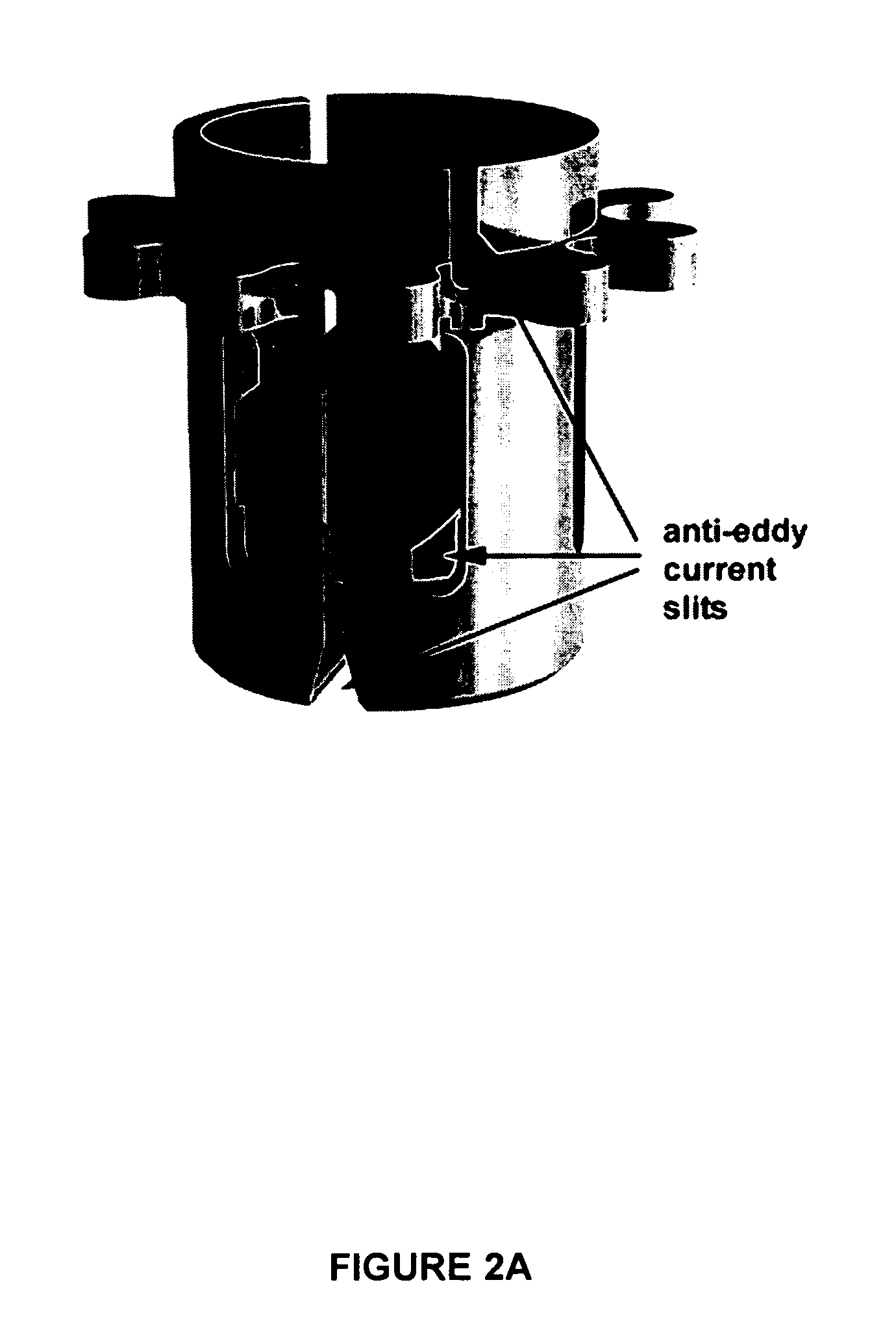
The purpose of the holes is to disrupt the natural path of electrons, so that it is difficult for eddy currents to form.
Method used
View moreImage
Smart ImageViewing Examples

Examples
example 1
Use of a Test Mass According to an Embodiment of the Present Invention Near an Electric or Magnetic Field
[0033] Perforated, conducting test masses of the present invention were used to replace conventional conducting, imperforated test masses in an FG5 interferometer located near a pumphouse containing an electric motor that produced a large electromagnetic field. Prior to the replacement of the test masses, interference affecting the accuracy of gravity measurements was observed due to the presence of large and unavoidable electromagnetic fields. Upon replacement of the conventional test masses with the perforated test masses, improved accuracy of about 5×10⁻⁷ m·s−2 was observed.
Login to View More PUM
 Abstract
The present invention provides devices and methods for reducing or eliminating sources of systematic errors in the measurement of absolute gravity or gravity field gradients; specifically, an improved test mass for an interferometer is disclosed that reduces the influence of nearby electromagnetic fields on a freefalling test mass.
Description
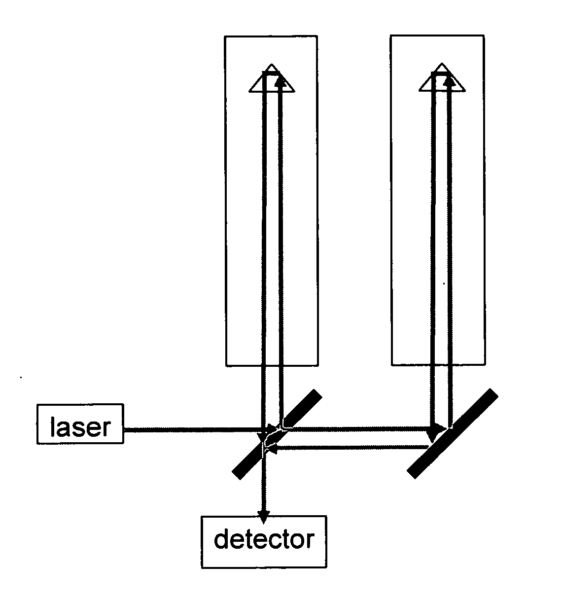
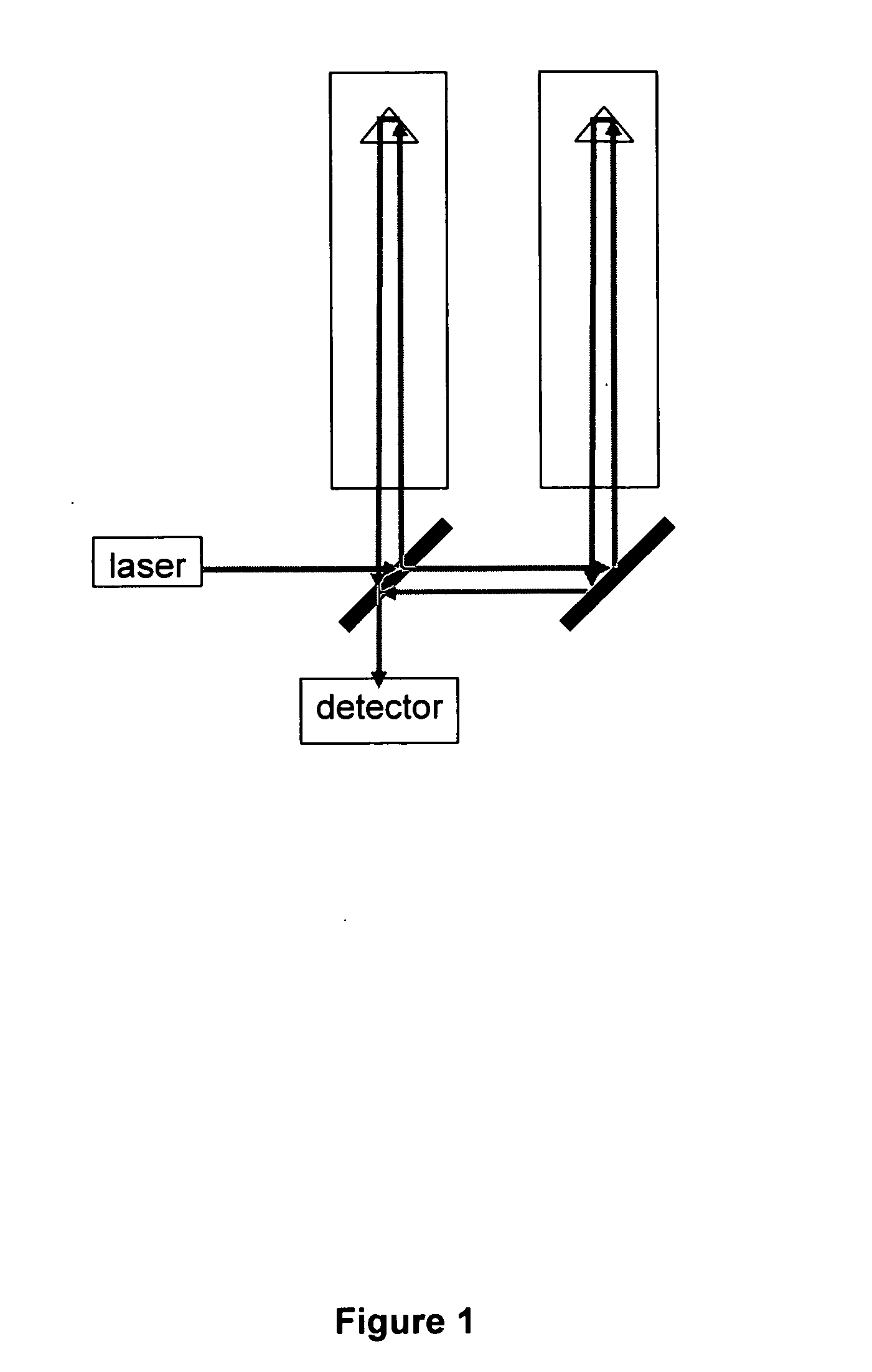
FIELD OF THE INVENTION [0001] The present invention relates to the measurement of absolute gravity and gravity field gradients using a measuring apparatus incorporating a test mass that is designed to avoid inaccuracies associated with nearby electromagnetic fields. BACKGROUND OF THE INVENTION [0002] Typical absolute gravimeters and gradiometers operate by tracking the freefall of an object, or “test mass”, within an instrument known as an interferometer. An interferometer contains a laser beam that is split into two paths, each portion of the laser beam reflects off a retro-reflector, contained within a test mass located in a vertical chamber. In one vertical chamber, a test mass containing a retro-reflector is placed in freefall. In the second vertical chamber, if the retro-reflector is held fixed, the signal at the combined output of the two beams can be used to determine the acceleration of gravity (g). If the retro-reflectors in both chambers are placed in freefall, the signal ...
Claims
Login to View More Application Information
Patent Timeline
 Patent Type & AuthorityApplications(United States)
IPC IPC(8): G01V7/00
CPCG01V7/14
InventorNIEBAUER, TIMOTHY M.BILLSON, RYAN M.KLOPPING, FRED J.VALENTINE, JESS G.VAN WESTRUM, DEREK C. S.
OwnerMICRO G LACOSTE