
System and method of air quality control for air-conditioning devices

a technology of air-conditioning devices and air quality control, which is applied in the direction of auxillary pretreatment, heating types, separation processes, etc., can solve the problems of increasing the risk of bioterrorism and infections of microorganism radiation does not help in controlling or reducing foul odors in the indoor air, and the purifier is an independent uni

Inactive Publication Date: 2006-06-22
GENERAL ELECTRIC CO
View PDF10 Cites 52 Cited by
  • Summary
  • Abstract
  • Description
  • Claims
  • Application Information

AI Technical Summary

Benefits of technology

"The patent describes an air quality control system for an air-conditioning unit. The system includes a housing with a source air inlet and an outlet for sanitized air. It also includes independently controllable air sanitizing components that can be controlled based on the air conditioning unit's operating state. The system uses ultraviolet radiation and ozone gas to control the quality of the air. The system can be electrically isolated from the air-conditioning device. The technical effect of this patent is to provide a system that can effectively control the quality of air in an air-conditioned environment."

Problems solved by technology

Moreover, there is ever increasing risk of bio-terrorism and infections from microbe-infested indoor air.
Furthermore, although bacteria and microbes present in the air may be killed by ultraviolet irradiation from the germicidal lamps, such radiation does not help in controlling or reducing foul odors in the indoor air.
These air purifiers are independent units and do not work in sync with room air-conditioners / dehumidifiers.
This makes purification of a large volume of air difficult without the use of multiple purification units.
Air purification in a hotel with a large number of rooms, for example, would require the use of a large number of such traditional air purifiers, which can easily translate into a very high cost.
Moreover, such traditional air purifiers require additional space, electrical power and human intervention / manual operation and control, which may not be suitable for many situations.

Method used


Image

  • System and method of air quality control for air-conditioning devices
  • System and method of air quality control for air-conditioning devices
  • System and method of air quality control for air-conditioning devices

Examples


Embodiment Construction

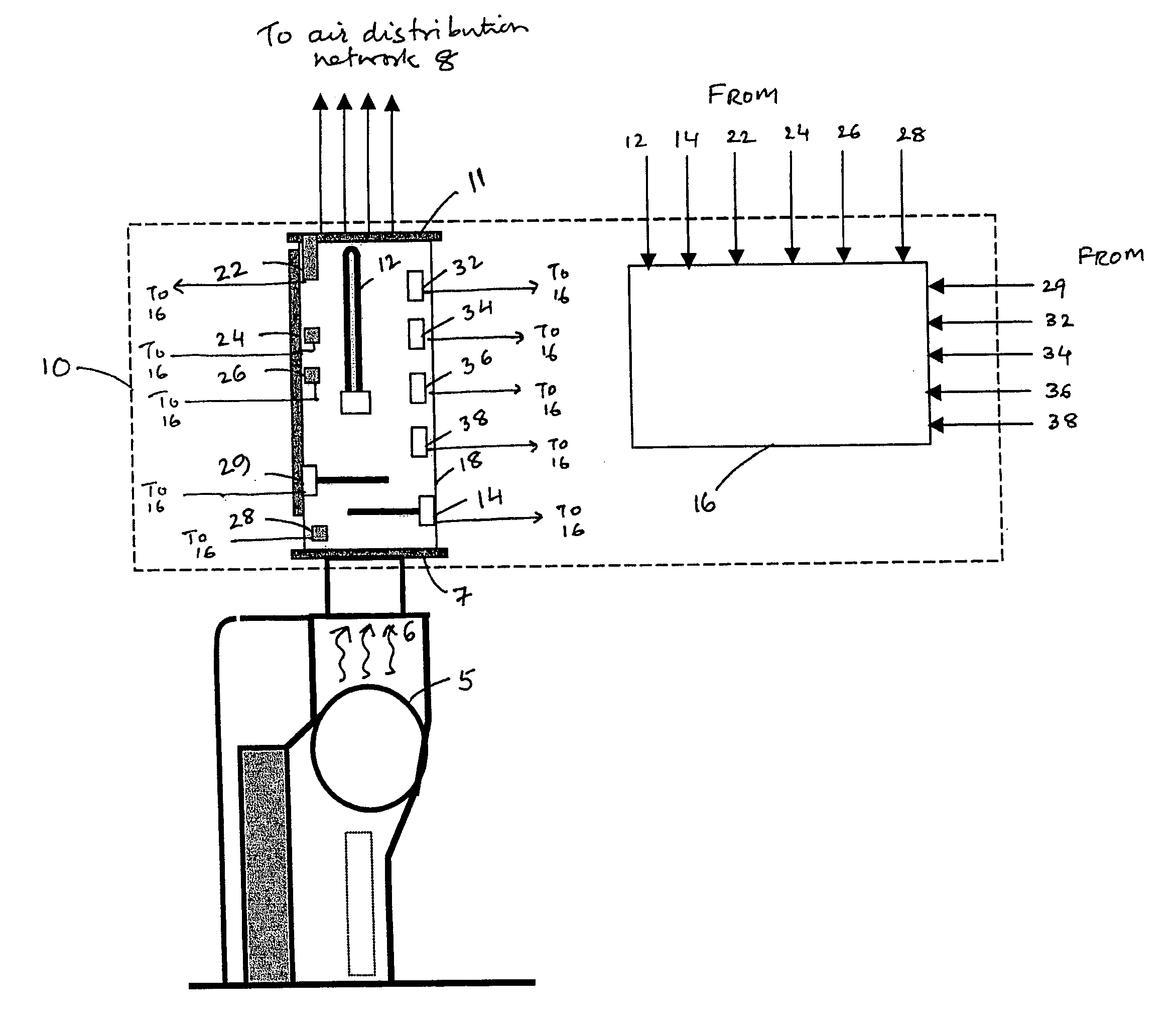
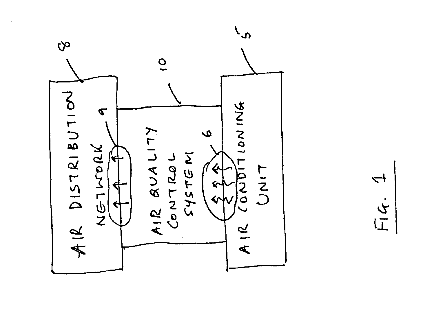
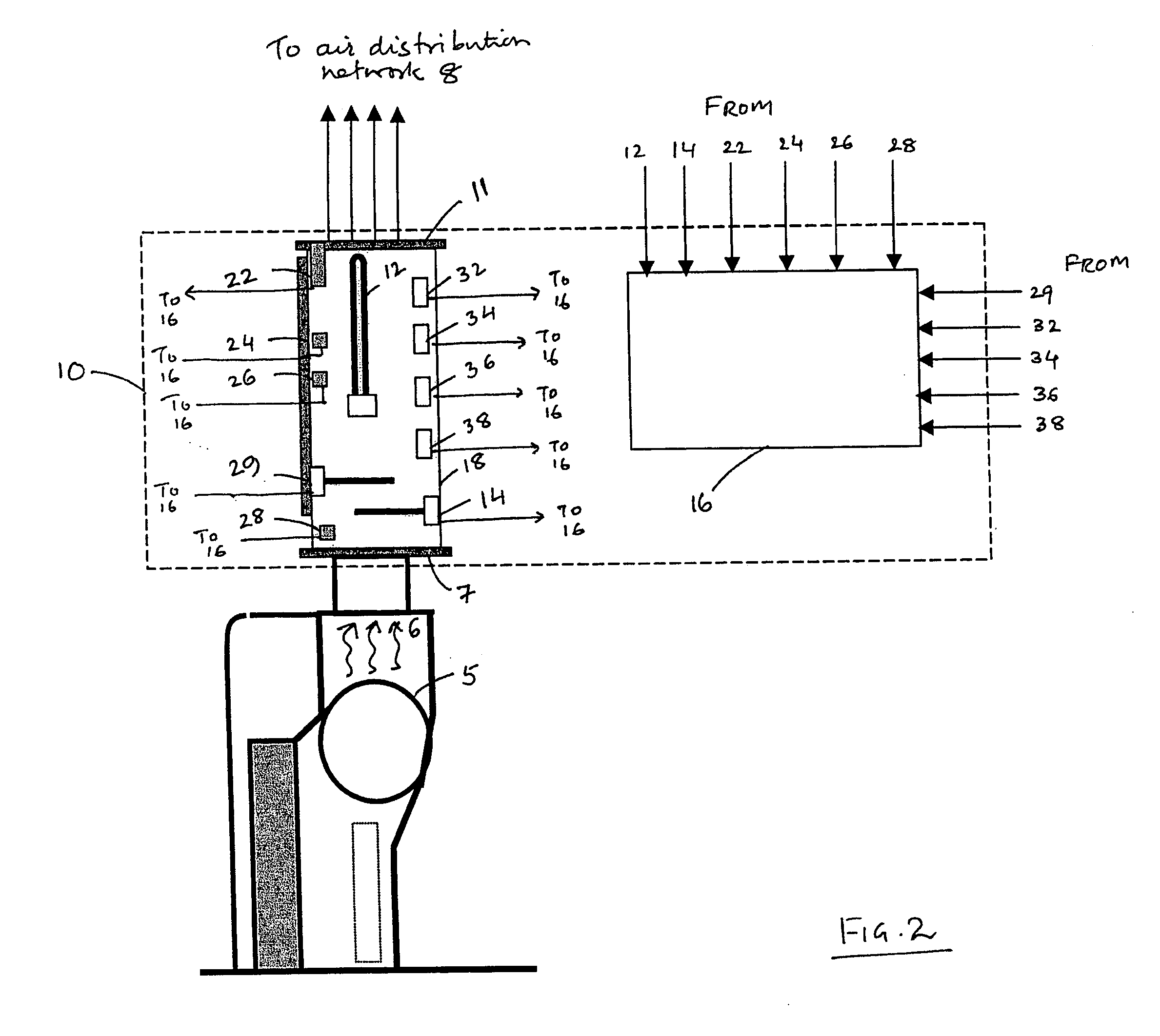
[0013]FIG. 1 illustrates an air quality control system 10 in accordance with one embodiment of the invention. In the illustrated embodiment, the air quality control system 10 is disposed between a conventional air conditioning unit 5 and a conventional air distribution network 8. In the description and claims to follow and unless otherwise indicated, the terms air conditioning unit, air conditioning device, and air conditioning system are intended to be synonymous and may be used interchangeably herein. Furthermore, such terms are intended to represent a broad class of devices, including but not limited to air coolers, air heaters, dehumidifiers, and humidifiers that operate to condition air. The air distribution network 8 may represent a conventional air airflow cabinet designed for use with the air conditioning unit 5 to distribute and / or direct conditioned air to one or more locations or objects. In one embodiment of the invention, the air quality control system 10 represents a m...


PUM

PropertyMeasurementUnit
wavelengthaaaaaaaaaa
resonance wavelengthaaaaaaaaaa
of wavelengthaaaaaaaaaa

Abstract

A system and method for air quality control system for an air-conditioning device. The air quality control system includes a housing having an inlet end to receive a source airflow from the air-conditioning unit and an outlet end to provide a sanitized airflow. The system also includes a number of independently controllable air sanitizing components coupled to the housing. The system further includes a controller to adaptively control which of the air sanitizing components should operate as a function of at least an operating state of the air conditioning unit.

Description

BACKGOUND [0001] Embodiments of the present invention relate generally to air conditioning and air cleaning, and more particularly to a system and method for controlling the quality of air emitted from air conditioning devices. [0002] Controlling quality of air emitted by air conditioning devices is important because a significant part of world population today lives under the threats of chronic lung diseases such as asthma and chronic bronchitis, which are caused by airborne pathogens. Moreover, there is ever increasing risk of bio-terrorism and infections from microbe-infested indoor air. Furthermore, although bacteria and microbes present in the air may be killed by ultraviolet irradiation from the germicidal lamps, such radiation does not help in controlling or reducing foul odors in the indoor air. [0003] Traditional air purifiers found in the prior art are typically stand-alone fan-units fitted with devices like germicidal lamps that are positioned in the recirculation air pat...

Claims


Application Information

Patent Timeline
Patent Type & Authority Applications(United States)
IPC IPC(8): B01J19/08B01D46/00
CPCA61L9/015A61L9/20B01D53/007B01D2251/104B01D2257/91F24F3/166F24F2003/1667F24F2003/1685F24F8/40F24F8/192F24F8/22Y02A50/20
Inventor JOSHI, ANAND GANESHWILSON, MARK WAYNESUBBARAO, GAUTAMUMAKANTHAN, HEMACHANDRAN
Owner GENERAL ELECTRIC CO
Learn More