Mixing bag with integral sparger and sensor receiver

a technology of sensor receiver and mixing bag, which is applied in the field of valves, can solve the problems of environmental contamination, contamination or leakage during mixing, and degradation of products, and achieves the effects of reducing the risk of environmental contamination, reducing the risk of contamination or leakage, and reducing the production efficiency

Active Publication Date: 2006-06-22
PALL TECH UK
View PDF41 Cites 70 Cited by
  • Summary
  • Abstract
  • Description
  • Claims
  • Application Information

AI Technical Summary

Benefits of technology

[0017] In another embodiment, a fluorescent sensor element is externally attached to the closed end of the tube. In such case, the invention further comprises the combination of the vessel with a fiber optic cable for transmitting light to the sensor element and receiving the light reflected therefrom. Use of such a sensor arrangement allows for various characteristics of the fluid to be observed in a substantially non-invasive fashion.

Problems solved by technology

One significant limitation or shortcoming of such an arrangement is the danger of contamination or leakage during mixing.
This opening provides an opportunity for bacteria or other contaminants to enter, which of course can lead to the degradation of the product.
A corresponding danger of environmental contamination exists in applications involving hazardous or toxic fluids, or suspensions of pathogenic organisms, since dynamic seals or bearings are prone to leakage.
Cleanup and sterilization are also made difficult by the dynamic bearings or seals, since these structures typically include folds and crevices that are difficult to reach.
In both cases, the bioreactors are not readily disposable and thus must be cleaned and sterilized before reuse for bioprocessing.
This presents the challenging task of providing inexpensive fluid-touching components that can be discarded along with the bag after use.
Another challenge is positioning the components of the bioreactor on the flexible bag.
Obviously, this method of component attachment does not work for plastic bags.

Method used


Image

  • Mixing bag with integral sparger and sensor receiver
  • Mixing bag with integral sparger and sensor receiver
  • Mixing bag with integral sparger and sensor receiver

Examples


Embodiment Construction

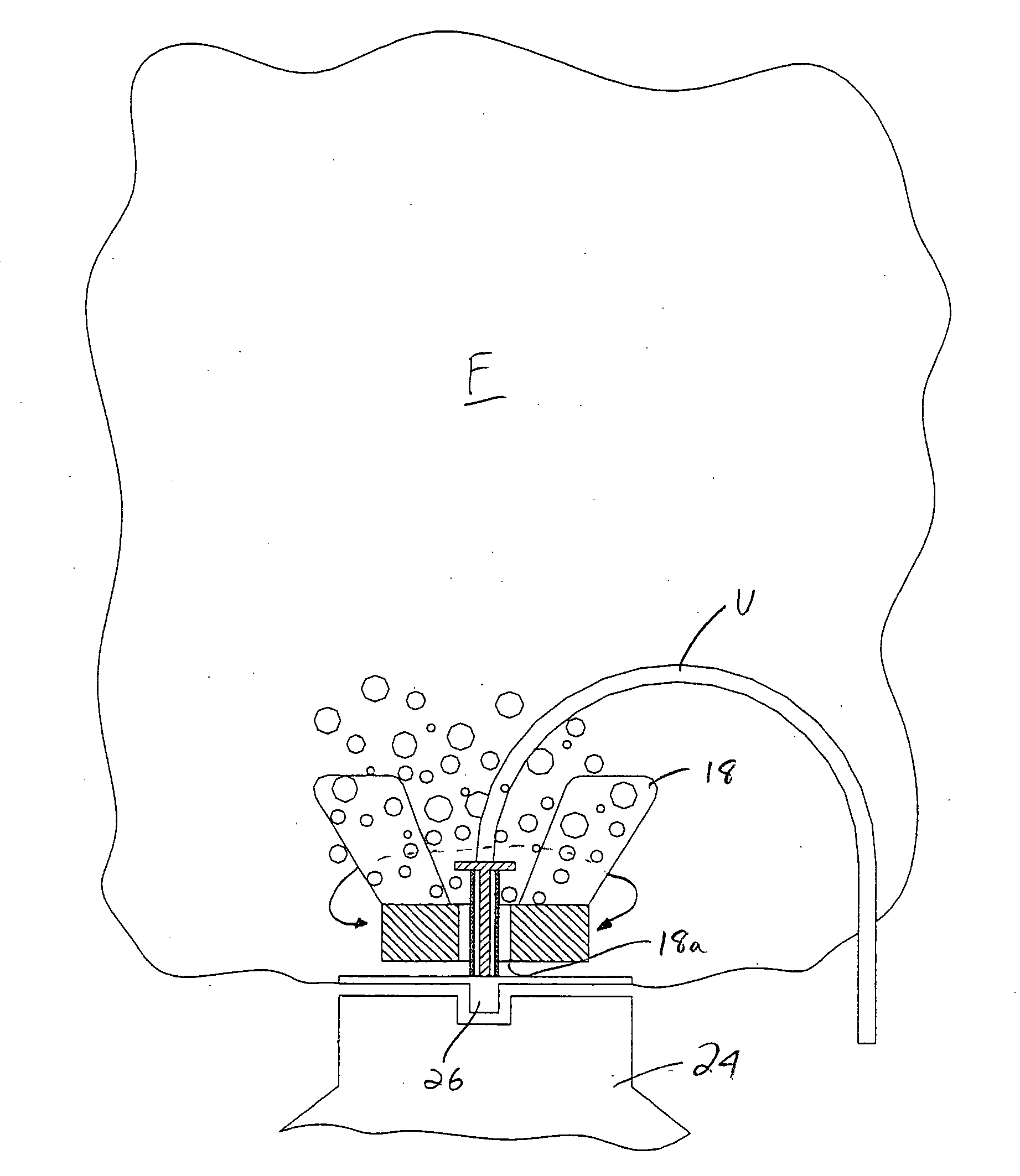
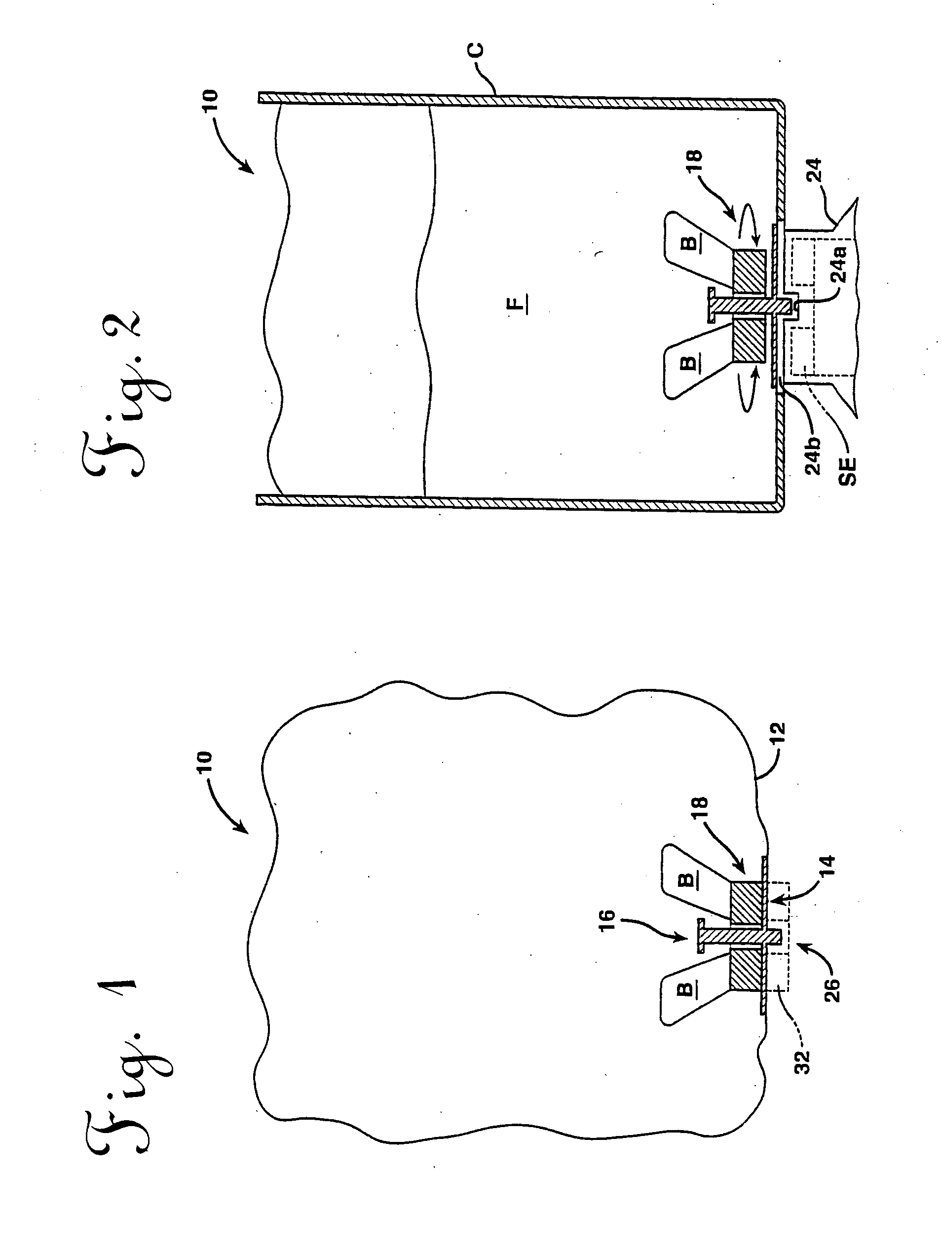
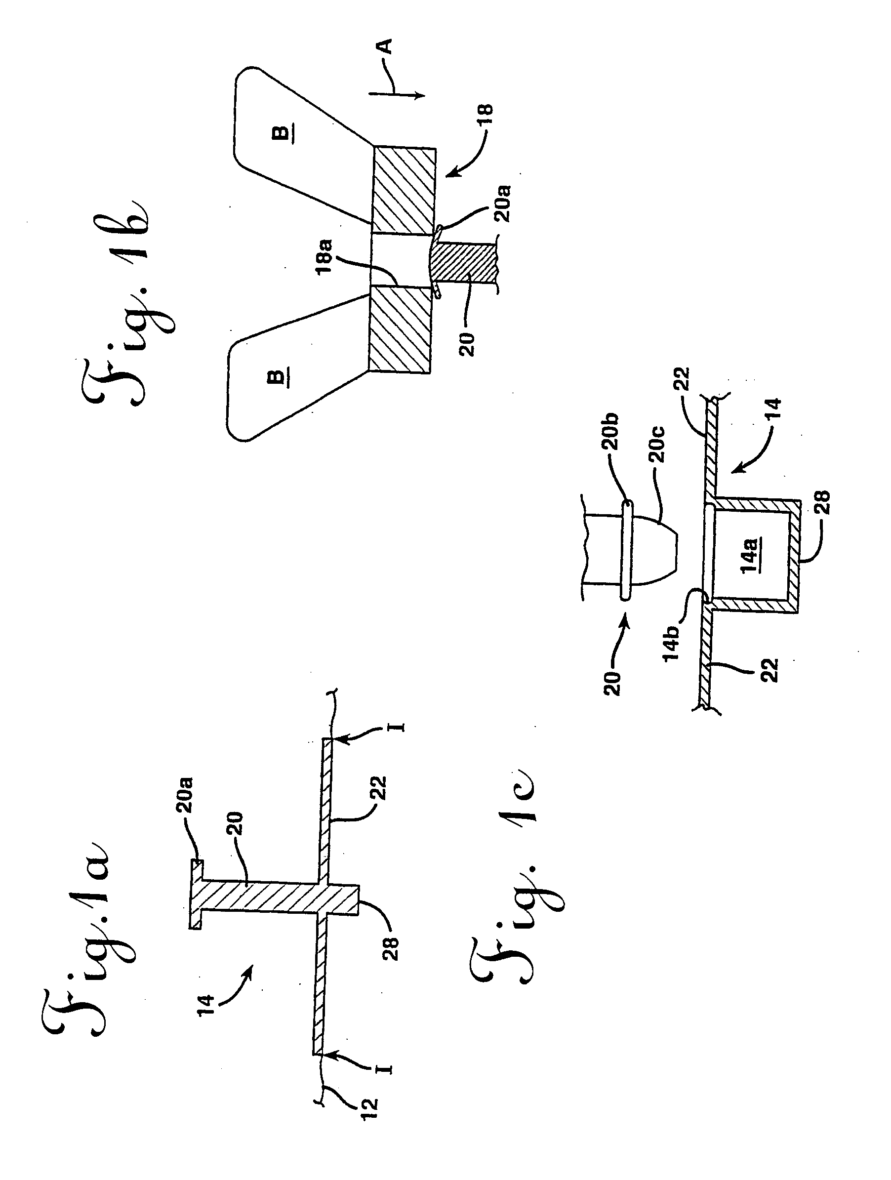
[0033] Reference is now made to FIG. 1, which discloses one embodiment of the vessel of the present invention in the form of a bag 10. In this embodiment, the bag 10 includes a body having a flexible or non-rigid portion 12, which is illustrated schematically, and a rigid or stiff portion 14, which is shown in cross-section. However, as outlined further in the description that follows, the use of the many of the present inventive concepts disclosed herein with vessels that are completely rigid is also possible.

[0034] The bag 10 may be hermetically sealed and may have one or more openings or fittings (not shown) for introducing or recovering a fluid. Alternatively, the bag 10 may be unsealed or open-ended. The particular geometry of the bag 10 employed normally depends on the application and is not considered critical to the invention. For example, in the case of a sterile fluid, a hermetically sealed, pre-sterilized bag with an aseptic fitting might be desirable; whereas, in the ca...


PUM

PropertyMeasurementUnit
thicknessaaaaaaaaaa
thicknessaaaaaaaaaa
permeableaaaaaaaaaa

Abstract

A mixing bag for use in bioprocessing in which a fluid is received and agitated using an internal fluid-agitating element driven by an external motive device is disclosed. The bag may include an integral sparger and sensor receiver. Related methods are also disclosed.

Description

[0001] This application is a continuation of PCT Patent Application Serial No. PCT / US2005 / 000464, filed Jan. 7, 2005, which claims priority to U.S. Provisional Patent Application Ser. No. 60 / 535,031, filed Jan. 7, 2004 and U.S. Provisional Patent Application Ser. No. 60 / 599,960, filed Aug. 9, 2004, the disclosures of which are all incorporated herein by reference.TECHNICAL FIELD [0002] The present invention relates generally to vessels in which fluids are agitated and, more particularly, to a mixing bag including an integral sparger and sensor receiver. BACKGROUND OF THE INVENTION [0003] Most pharmaceutical solutions and suspensions manufactured on an industrial scale require highly controlled, thorough mixing to achieve a satisfactory yield and ensure a uniform distribution of ingredients in the final product. Agitator tanks are frequently used to complete the mixing process, but a better degree of mixing is normally achieved by using a mechanical stirrer or impeller (e.g., a set o...

Claims


Application Information

Patent Timeline
Patent Type & Authority Applications(United States)
IPC IPC(8): B01F3/04B01F7/16B01F15/00
CPCB01F3/04248C12M23/22B01F3/04531B01F7/162B01F13/08B01F13/0827B01F15/00207B01F15/00824B01F15/0085B01F2215/0037C12M23/14C12M27/02C12M29/06B01F13/00B01F15/00123B01F3/04262B01F23/23121B01F23/23123B01F23/233B01F27/808B01F33/45B01F33/453B01F35/213B01F35/50B01F35/513B01F2101/23B01F33/4534B01F35/20B01F33/00
Inventor TERENTIEV, ALEXANDRE N.TERENTYEV, SERGEY
Owner PALL TECH UK
Why Eureka
Try Eureka