Mobile phase treatment for chromatography

a technology of chromatography and mobile phase, which is applied in the direction of filtration separation, separation processes, instruments, etc., can solve the problems of compromising separation efficiency and peak shape, affecting the resolution of loss, etc., to achieve convenient temperature programming of the mobile phase, convenient and efficient method, and rapid equilibration

Inactive Publication Date: 2006-03-16
SELERITY TECH
View PDF10 Cites 33 Cited by
  • Summary
  • Abstract
  • Description
  • Claims
  • Application Information

AI Technical Summary

Benefits of technology

[0010] This invention provides a convenient and efficient method for heating or cooling the mobile phase fluid of a chromatographic system prior to its entry into the chromatographic column. The “preheating” or “precooling” process is carried out using an apparatus containing a short length of tubing where the mobile phase is heated or cooled. The heating or cooling is performed using a heating or cooling element that is in intimate thermal contact with the exterior of the tubing. The temperature change of the mobile phase is measured downstream by a non-invasive, low-mass sensing element on the exterior of the tubing. With a low mass heating or cooling element, the device can be very responsive and allows for rapid equilibration and convenient temperature programming of the mobile phase. This configuration also requires only a short contact time, is non-invasive, adds no dead volume, and allows for use of columns over a wide range of internal diameter, flow rates and temperatures.

Problems solved by technology

These temperature gradients can produce fluid channeling within the column and analyte retentive differences, compromising separation efficiency and peak shape.
Because of the limitations that can be imposed by some injection valves (particularly at high temperatures) and the complexities of handling hot solutions, some have resorted to an alternate technique.
This technique lessens the burden of heating the fluid after injection, but dilutes the sample and potentially damages separation efficiency by adding dead volume when the two streams are mixed.
Unfortunately, such long lengths of tubing can contribute to resolution loss even when the tubing is small in diameter.
This method introduced the temperature probe in the flow path that added significantly to the system dead volume and potentially contaminated the fluid.
While dead volume is not a great concern with wide bore columns (e.g., greater than a 4.6 mm inner diameter), its effect can be more of a problem with microbore columns.
Additional disadvantages exist in that the assembly used to support the temperature probe also supplies mass that must be heated to obtain a stable temperature reading.
This additional mass can also contribute to delays in implementing a temperature change by requiring a significant equilibration time.
Other cumbersome methods have been used to heat the mobile phase to the desired temperature, but such methods are not very effective or convenient.

Method used


Image

  • Mobile phase treatment for chromatography
  • Mobile phase treatment for chromatography
  • Mobile phase treatment for chromatography

Examples


example 1

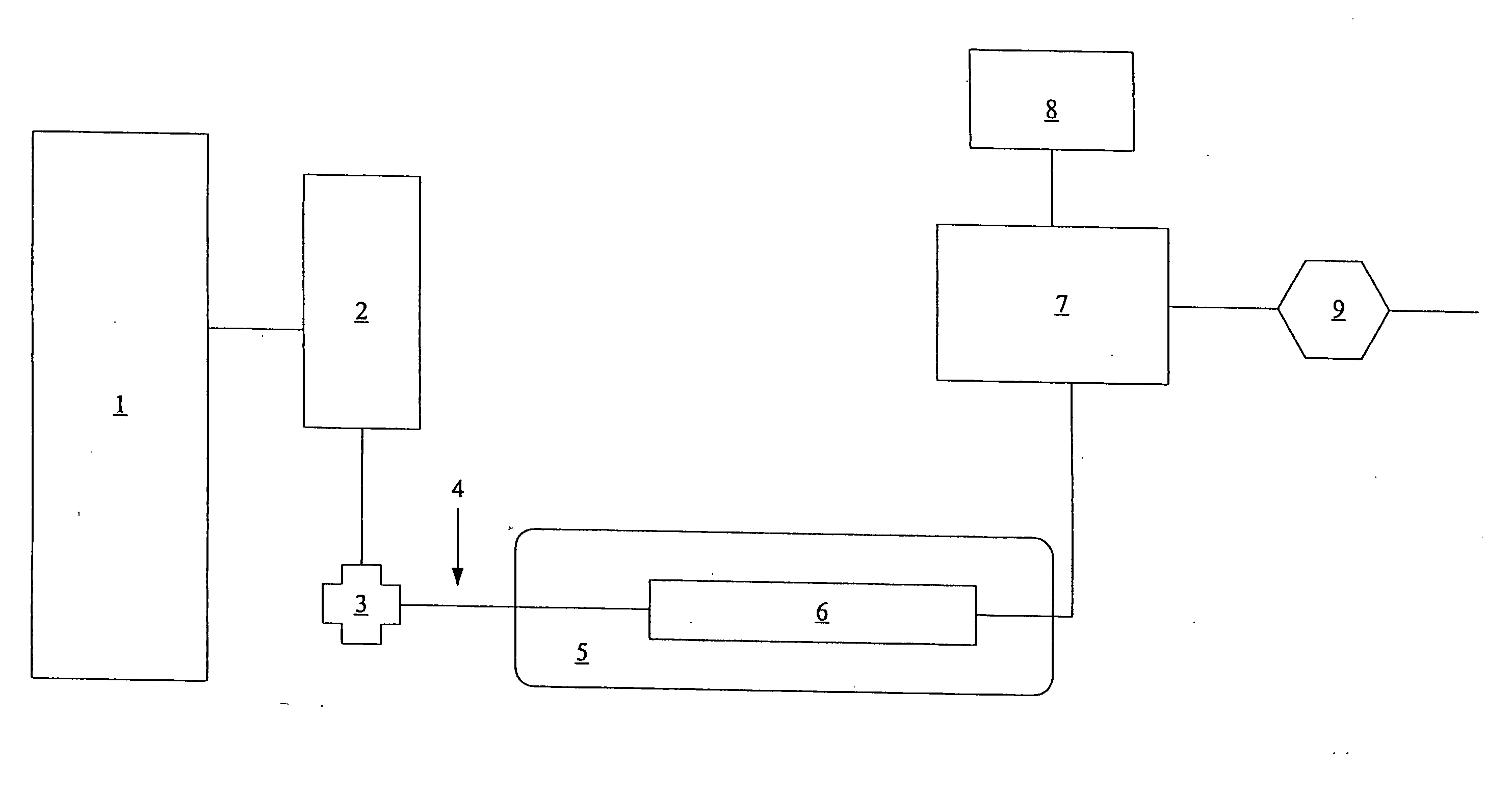
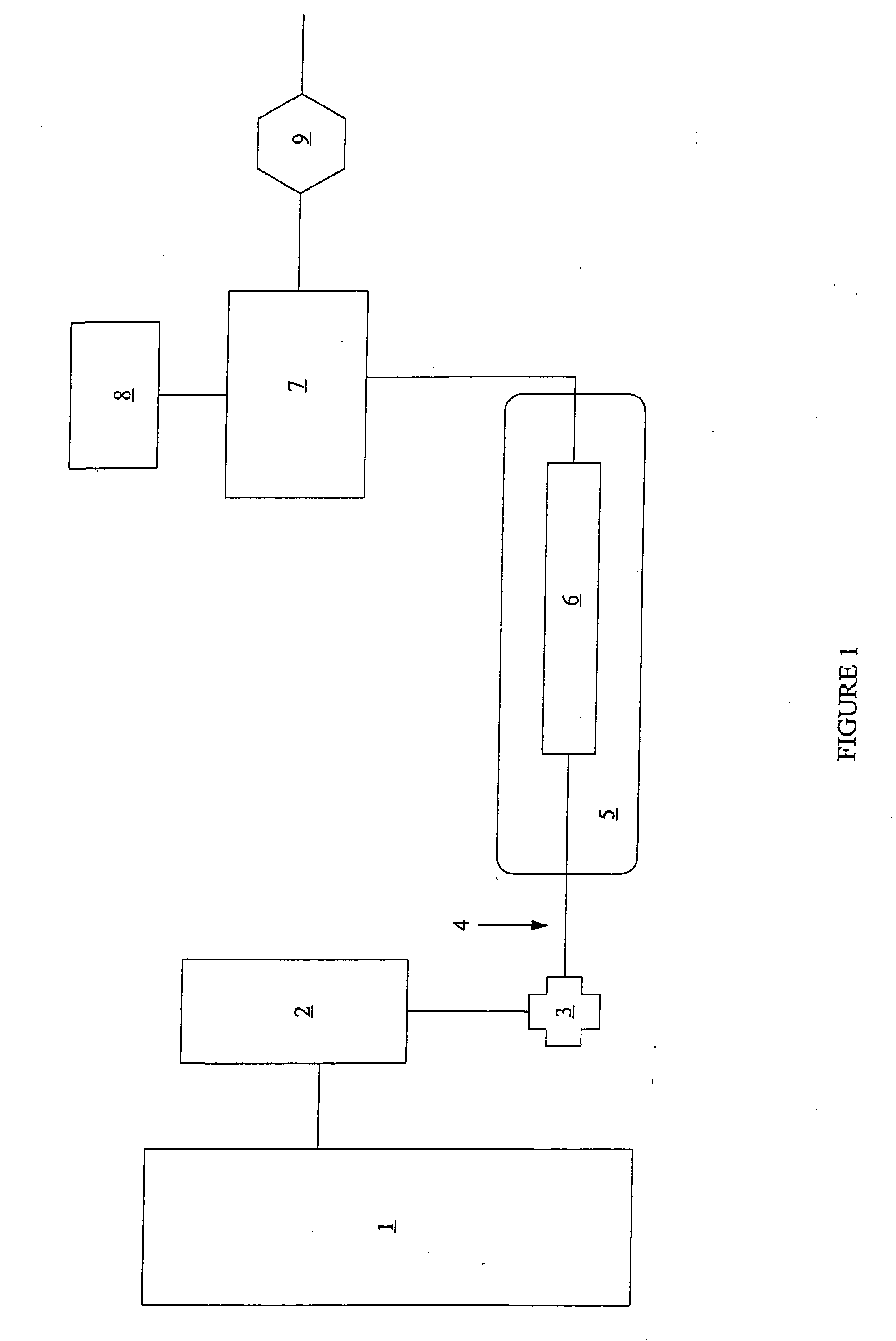
[0043] 15 cm sections of 0.005″ and 0.007″ (inner diameter)× 1 / 16″ (outer diameter) stainless steel tubing were potted in aluminum cans. The potting mix was a Duralco High Temperature Epoxy Resin fortified with 35% by weight of aluminum powder. A recess was machined into a 1.25″ diameter aluminum rod to accept a heater cartridge, which was held in place with an insulated C-clamp. A 1.25″ diameter clamp heater of 200 watts was attached to the outside of the aluminum rod, and a temperature sensor was imbedded in a hole drilled in the bottom of the rod such that the block temperature could be monitored.

[0044] A short distance from the heater assembly, a small type J thermocouple was soldered to the outside of the stainless steel tubing extending out from the can. The flow of water through the tubing was controlled with a Knauer HPLC pump. An Alltech 300 psi backpressure regulator was coupled to the outlet of the tube to prevent boiling of the water inside the heated zone when the devi...

example 2

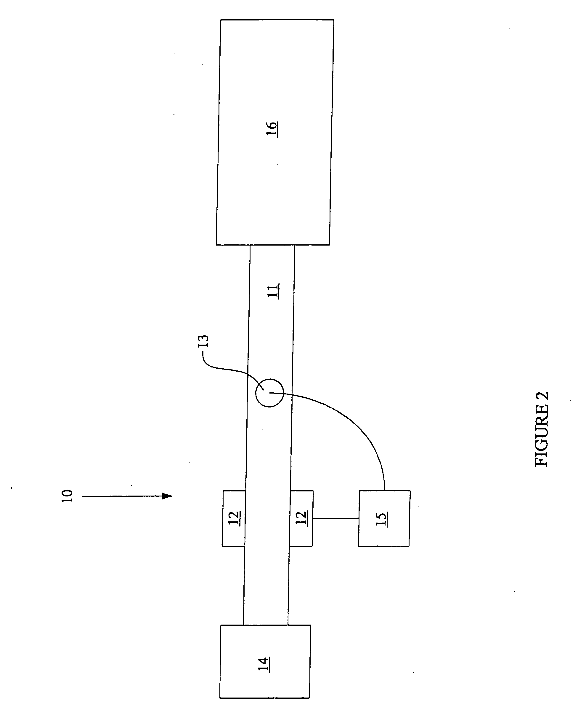
[0046] The heater portion of the apparatus in Example 1 was simplified by attaching a short heater cartridge with silver solder directly to a piece of 0.005″× 1 / 16″ stainless steel tubing and using it as a connector between an injector valve and separation column. A thermocouple was soldered directly to the outside wall of the stainless steel tubing 0.25 inches downstream from the heater cartridge. The power from the temperature controller to the heater was varied using pulse width modulation (from an incandescent light dimmer). Using this assembly, phenanthrene was eluted with 13840 theoretical plates and a peak width at half height of 0.89 seconds from a 10 cm ZirChrom PDB column (4.6 mm id, 3 micron particles, 300 Angstrom pore size, Zirchrom Separations) in 46 seconds using 35% acetonitrile in water at 3 mil / min and 150 degrees C. A 2.5 microliter injection loop was used along with a UV detector at 254 nm.

[0047] With all other parameters substantially the same except active pre...

example 3

[0048] The heater portion of the apparatus in Example 1 was modified by attaching one end of a piece of glass fiber insulated 30 gauge Nichrom 80 wire that was 15 inches long to the 0.005 inch internal diameter stainless steel tube. The wire was wrapped tightly against the stainless steel tubing and secured in place with high temperature epoxy. An insulated connection was made to TFE coated copper wire, and in the same vicinity, another TFE insulated copper wire was attached to the stainless steel tubing as a ground line to complete the circuit. The stainless steel tubing was insulated with a small piece of 70 micron thick polyimide tape, and a thermocouple was placed against it and secured with Teflon heat shrink tubing. A water mobile phase was pumped through the tubing and energy was transferred into it from the resistance wire by applying a DC voltage from 0.06 to 24 volts. The water was heated in accordance with the amount of power supplied. The temperature feedback and voltage...


PUM

PropertyMeasurementUnit
lengthaaaaaaaaaa
lengthaaaaaaaaaa
massaaaaaaaaaa

Abstract

A convenient and efficient method for heating or cooling the mobile phase fluid of a chromatographic system prior to its entry into the chromatographic column is described. The “preheating” or “precooling” process is carried out using an apparatus containing a short length of tubing where the mobile phase is heated or cooled. The heating or cooling is performed using a heating or cooling element that is in intimate thermal contact with the exterior of the tubing. The temperature change of the mobile phase is measured downstream by a non-invasive, low-mass sensing element on the exterior of the tubing. With a low mass heating or cooling element, the device can be very responsive and allows for rapid equilibration and convenient temperature programming of the mobile phase. This configuration also requires only a short mobile phase contact time, is non-invasive, adds no dead volume, and allows for use of columns over a wide range of internal diameter, flow rates and temperatures.

Description

REFERENCE TO RELATED APPLICATIONS [0001] This application claims priority from U.S. provisional patent application No. 60 / 358,926, the entire disclosure of which is incorporated herein by reference.FIELD OF THE INVENTION [0002] The invention generally relates to mobile phases and their use in chromatography. In particular, the invention relates to mobile phases and their use in High Performance Liquid Chromatography (HPLC). More particularly, this invention relates to a process for treating-including heating and / or cooling—and monitoring the fluids that are used as mobile phases in HPLC. BACKGROUND OF THE INVENTION [0003] In the field of analytical chemistry, there has recently been an increasing emphasis on using chromatography, especially HPLC. HPLC is a tool for analyzing mixtures by separating their various components. Typically, as shown in FIG. 1, an HPLC analysis is performed with an instrument containing a solvent reservoir 1, a pump 2, an injector 3, connection tubing 4, a ...

Claims


Application Information

Patent Timeline
Patent Type & Authority Applications(United States)
IPC IPC(8): B01D15/08B01D15/16G01N30/30
CPCB01D15/161G01N30/30G01N2030/3007G01N2030/3046G01N2030/303G01N2030/3038G01N2030/3023
Inventor JONES, BRIANPORTER, NATHANL
Owner SELERITY TECH
Why Eureka
Try Eureka