Flexible display designed for minimal mechanical strain

a flexible display and mechanical strain technology, applied in the field of electronic displays, can solve the problems of changing the thickness of the crystal layer, the natural flexibility of the plastic substrate, and the display utilizing glass substrates is less suitable, so as to achieve the effect of minimizing and/or eliminating mechanical strain in flexible electronic structures

Inactive Publication Date: 2006-06-22
EASTMAN KODAK CO
View PDF4 Cites 174 Cited by
  • Summary
  • Abstract
  • Description
  • Claims
  • Application Information

AI Technical Summary

Benefits of technology

[0013] The invention provides a method to minimize and / or eliminate mechanical strain in flexible electronic structures. The method is applicable to multi-layer electronic structures constructed from a variety of flexible materials.
[0014] In answer to the aforementioned and other problems of the prior art the invention provides a display device comprising a flexible substrate, an electrical optical display element comprising at least one conductive layer adjacent to the display wherein at least one of the conductive layers has an elongation to break of less than 2 percent and a balancing layer wherein the balanced display is capable of being formed to a radius of curvature of 10 cm or less without damage.

Problems solved by technology

On the other hand, under bending moments, the rigid display tends to lose its image over a large area, due to the fact that the gap between the substrates changes, thereby causing the liquid crystal material to flow away from the bending area, resulting in a changed crystal layer thickness.
Consequently, displays utilizing glass substrates are less suitable, when a more flexible or even bendable display is desired.
However, the natural flexibility of the plastic substrates presents problems, when trying to manufacture liquid crystal displays in a traditional manner.
The flexibility of the display is limited by the bending limitation of the display enclosures.
US Patent Application 2003 / 0214612 describes the use of sliding laminar layers in addition to the display element in order to reduce the strain on the display element but this approach involves requires a more complicated manufacturing procedure and does not lead to the ability to bend the display to small radii of curvature.
In one embodiment it is disclosed that “applying a layer to the capping material side of the released system to form a configuration wherein the system is substantially within a bending-strain reduced neutral plane.” This method has a distinct disadvantage in that it requires a complicated manufacturing process and no information is disclosed with respect to composition and / or thickness of the capping layer.
In both cases, the implementation of such an approach is rather complex, requiring either the iterative testing, or the skills and knowledge of Finite Element Method and Analysis, as well as familiarity of commercial simulation software.
The use of these displays and the manufacturing process may result in mechanical strain when the display is bent.
In particular, it is the conductive layers in the display that will experience strain during the bending process, and that will result in their breaking and making the device unusable.
ITO layers typically found in electronic displays are particularly sensitive to strain and will often fracture if subjected to an elongation of less than 1% of their total length.

Method used


Image

  • Flexible display designed for minimal mechanical strain
  • Flexible display designed for minimal mechanical strain
  • Flexible display designed for minimal mechanical strain

Examples


Embodiment Construction

[0024] The invention has numerous advantages over prior art flexible optical display devices. It allows more freedom in designing smaller and more rugged devices. It also makes it possible to produce curled displays. Another advantage of using flexible substrates is that a plurality of display devices can be manufactured simultaneously by means of continuous web processing such as, for example, reel-to-reel processing. The manufacture of one or more display devices by laminating (large) substrates is alternatively possible. Dependent on the width of the reels used and the length and width of a reel of (substrate) material, a great many separate (display) cells or (in the case of “plastic electronics”) separate (semi-) products can be made in these processes. Such processes are therefore very attractive for bulk manufacture of said display devices.

[0025] These and other advantages will become apparent from the detailed description below.

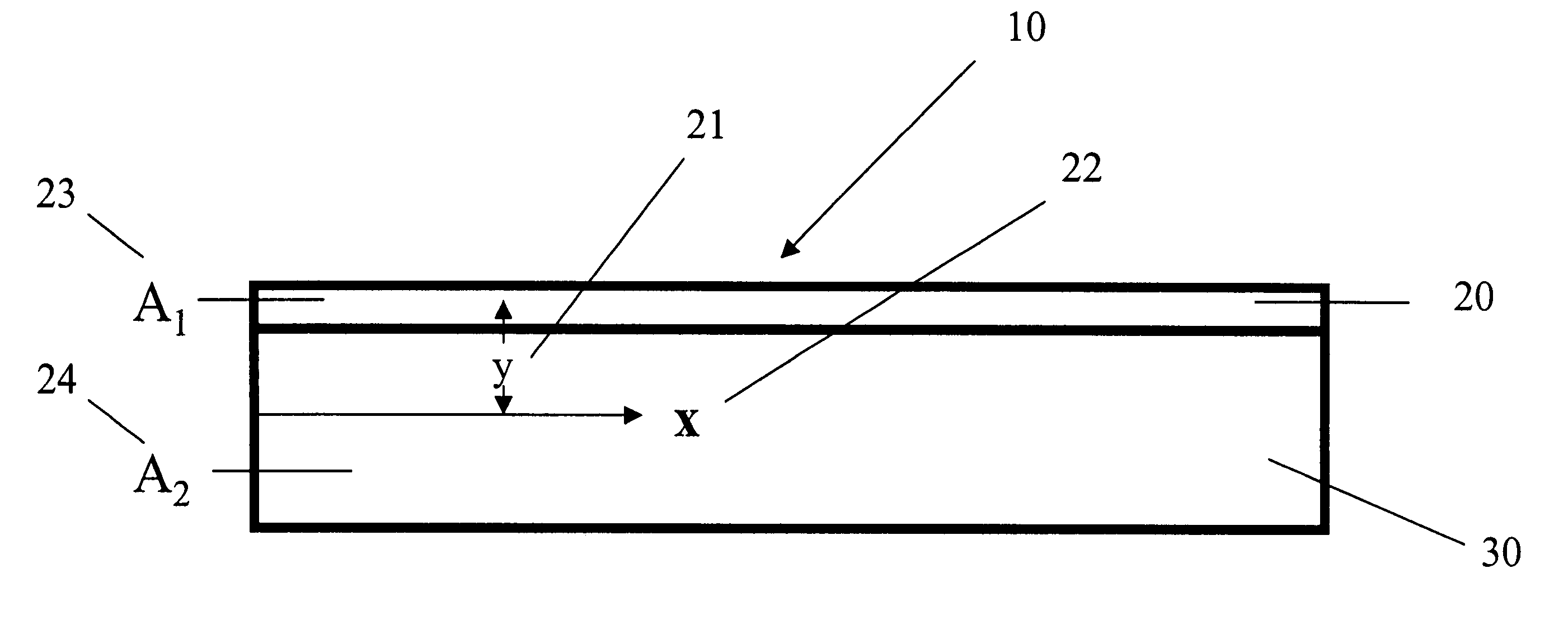
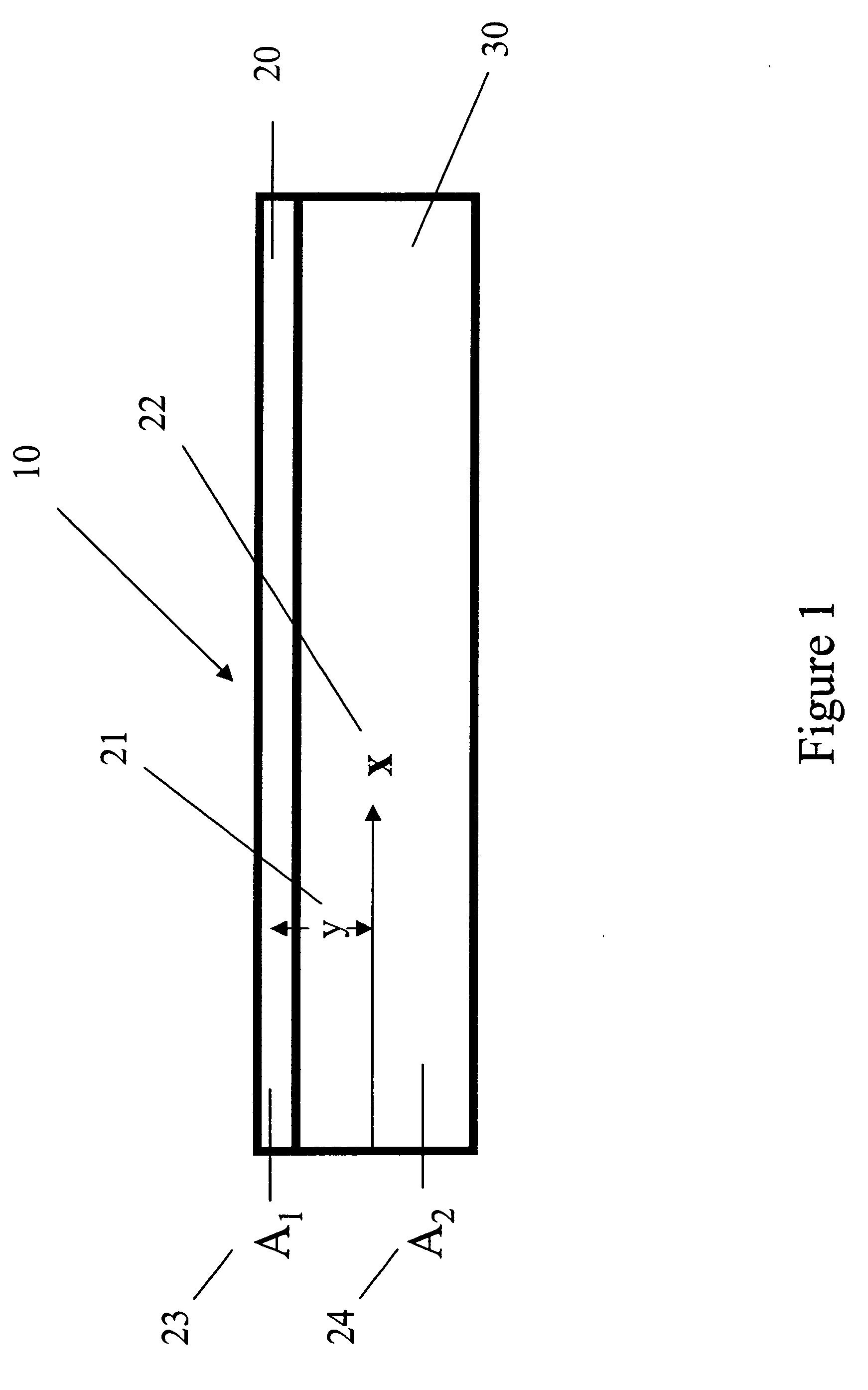
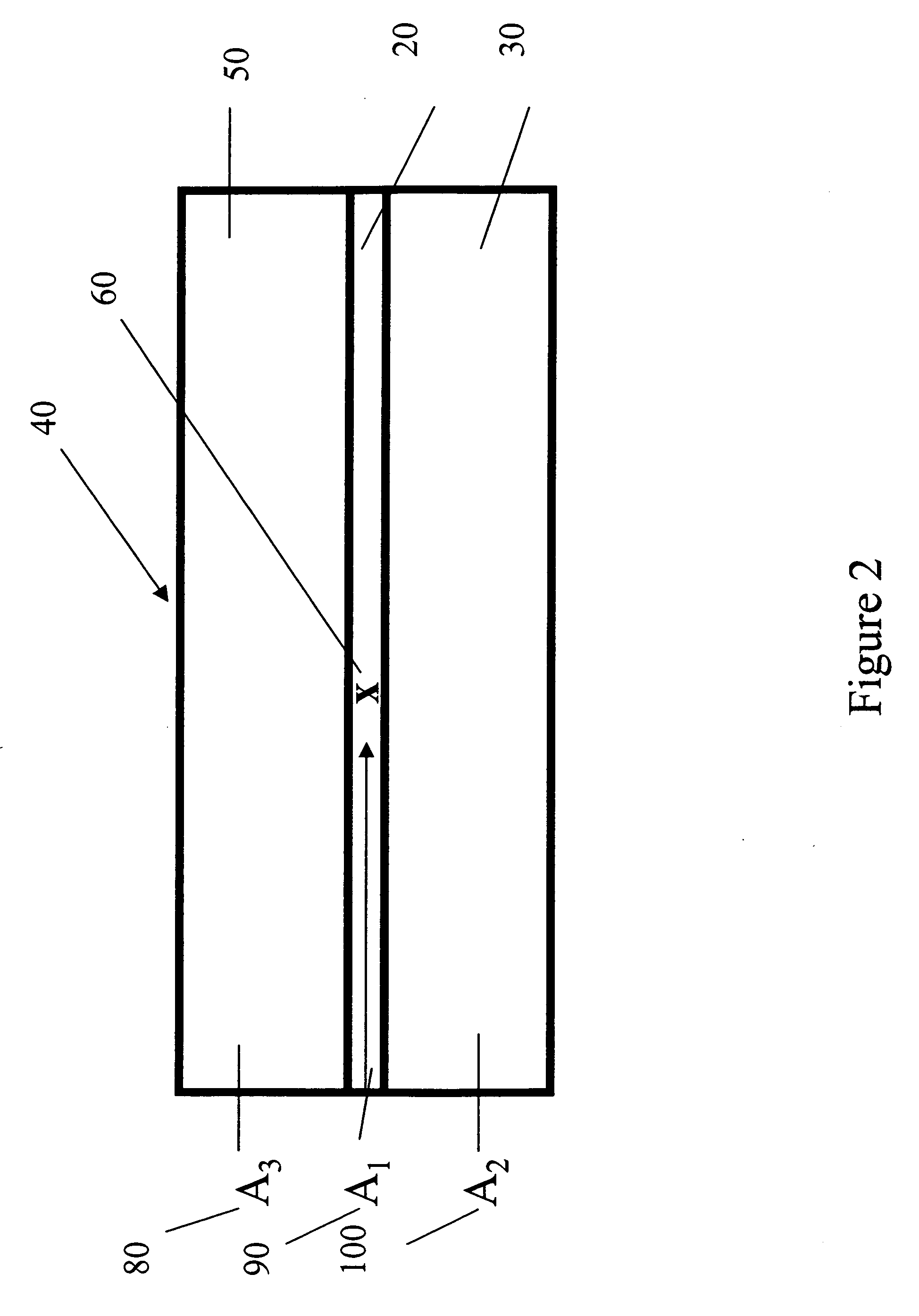
[0026] First, the means of calculating the st...


PUM


Abstract

The invention relates to a balanced optical display comprising a flexible substrate, an electrical optical display element comprising at least one conductive layer adjacent to the display element wherein at least one of the conductive layers has an elongation to break of less than 2 percent, and a balancing layer on the side opposite to the substrate, wherein the thickness and Young's modulus of each layers of the display is selected in such a way so that the display capable of being formed to a radius of curvature of 10 cm without damage.

Description

FIELD OF THE INVENTION [0001] This invention is in the field of electronic displays and, more particularly, it is in the field of a design to minimize mechanical strain in the manufacture or use of a flexible electronic display. BACKGROUND OF THE INVENTION [0002] Most of commercial displays devices, for example, liquid crystal displays (LCD), or solid-state organic light-emitting diode (OLED) are rigid. LCD comprises two plane substrates, commonly fabricated by a rigid glass material, and a layer of a liquid crystal material or other imaging layer, and arranged in-between said substrates. The glass substrates are separated from each other by equally sized spacers being positioned between the substrates, thereby creating a more or less uniform gap between the substrates. Further, electrode means for creating an electric field over the liquid crystal material are provided and the substrate assembly is then placed between crossed polarizers to create a display. Thereby, optical changes...

Claims


Application Information

Patent Timeline
Patent Type & Authority Applications(United States)
IPC IPC(8): H05B33/26H05B33/00
CPCG02F1/133305H01L51/52H01L51/5206H01L51/5237H01L2251/5338H10K50/80H10K50/81H10K50/841H10K2102/311
Inventor GAO, ZHANJUNWIEN, RICHARD W.EBRAHIM, TABREZ Y.
Owner EASTMAN KODAK CO
Why Eureka
Try Eureka