System and technique for calibrating radar arrays

a radar array and radar technology, applied in the field of radar systems and methods, can solve the problems of inability to combine coherently, lack of signal coherence between radars, measurement inaccuracy, etc., and achieve the effect of better detecting a targ

Active Publication Date: 2006-06-22
RAYTHEON CO
View PDF32 Cites 32 Cited by
  • Summary
  • Abstract
  • Description
  • Claims
  • Application Information

AI Technical Summary

Benefits of technology

[0009] The system and techniques of the present invention provide a calibration among a plurality of radar antenna arrays positioned in relatively close proximity to each other that allows coherent combination of signals associated with the plurality of radar arrays. The calibration simultaneously generates calibration factors for both the transmit and receive radar functions. The calibration accurately determines the relative location of the phase centers of the plurality of radar arrays, and the relative internal time delays among the plurality of radar systems, and provides calibration factors accordingly. The plurality of radar arrays can be controlled to cohere in any desired direction analogous to the way in which the subarrays in a single array would be controlled to steer that array in any desired direction. Accurately knowing the relative positions and relative time delays of the radar arrays allows subsequent application of relative time delays between radar arrays in order to cohere the radars in both transmit and receive modes.
[0011] With this particular arrangement, the method provides the ability to coherently combine the plurality or radars with only a small amount of processing loss compared to an ideal coherent processing gain, and therefore, to better detect a target.
[0013] With this particular arrangement, the system provides the ability to coherently combine the plurality or radars with only a small amount of processing loss compared to an ideal coherent processing gain, and therefore, to better detect a target.

Problems solved by technology

However, since the antennas of different ones of the plurality of radars are physically separated, the signals they receive as echoes from a target are generally not in phase, and therefore, do not combine coherently.
However, it is generally not sufficient that the position of the radar arrays merely be mechanically measured, since the distance between the radar arrays can be quite large compared to a radar signal wavelength, resulting in measurement inaccuracy.
Also, radar systems can introduce relative time delay differences according to different time delays of their respective transmit and receive electronics, which can result in substantial time delay differences between radar systems, also resulting in lack of signal coherency between radars.
One of ordinary skill in the art will understand that calibrating the relative positions and relative time delay differences of a plurality of radar arrays is difficult and subject to increasing errors as the separation of the plurality of radars increases.

Method used


Image

  • System and technique for calibrating radar arrays
  • System and technique for calibrating radar arrays
  • System and technique for calibrating radar arrays

Examples


Embodiment Construction

[0023] Before describing the system and method for calibrating radar arrays of the present invention, some introductory concepts and terminology are explained. As used herein, the term monostatic refers to operation of a single radar, in which the radar transmits a radar signal, the radar signal propagates to and echoes from a target, and the echo is received by the single radar. As used herein, the term bistatic refers to operation of more than one radar, for example first and second radars, in which the first radar transmits a radar signal, the radar signal propagates to and echoes from a target, and the echo is received by the second radar. As used herein, the term “radar array” refers to a radar antenna having a plurality of radar elements. However, the concepts used herein apply equally well to a radar antenna having any form of construction.

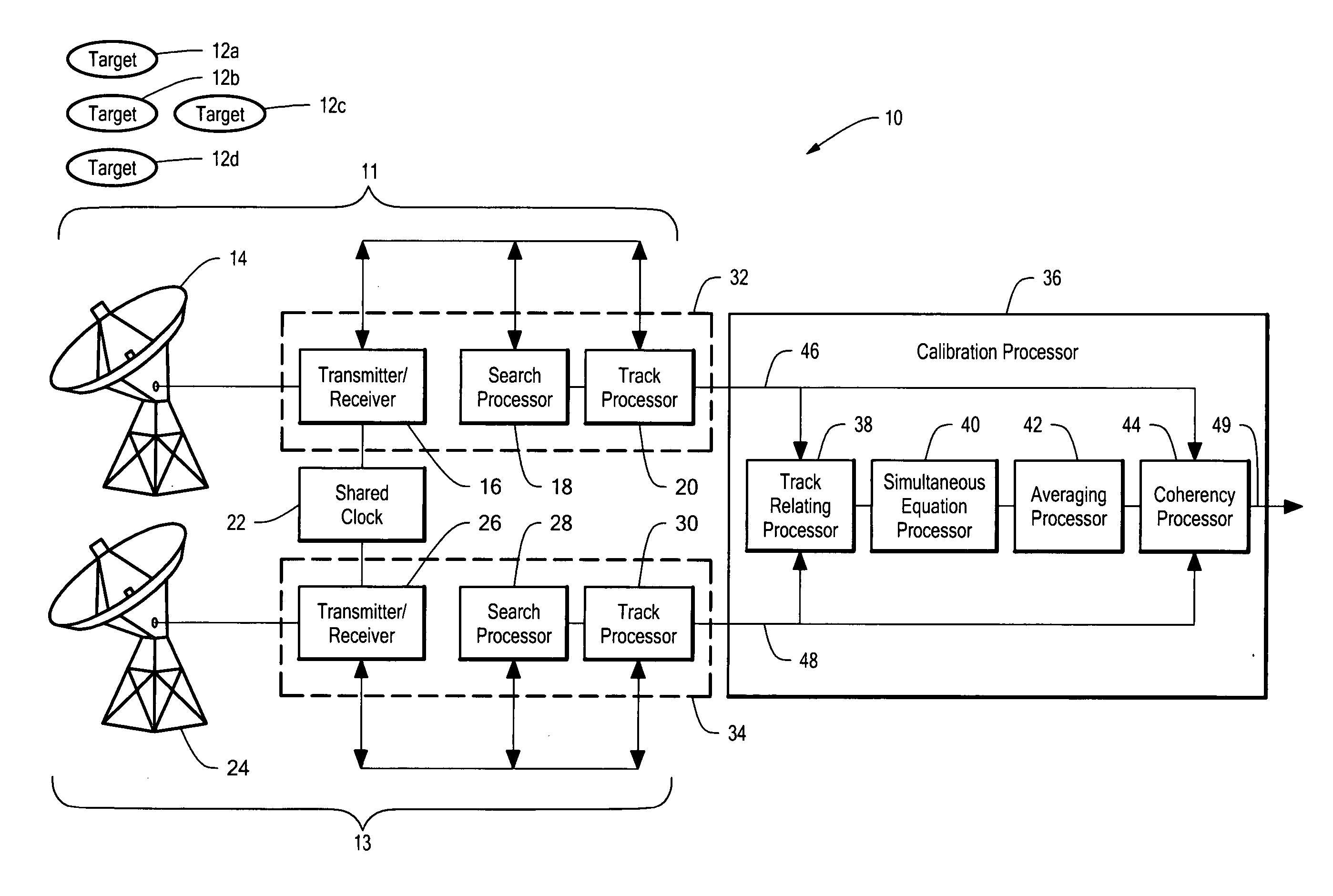
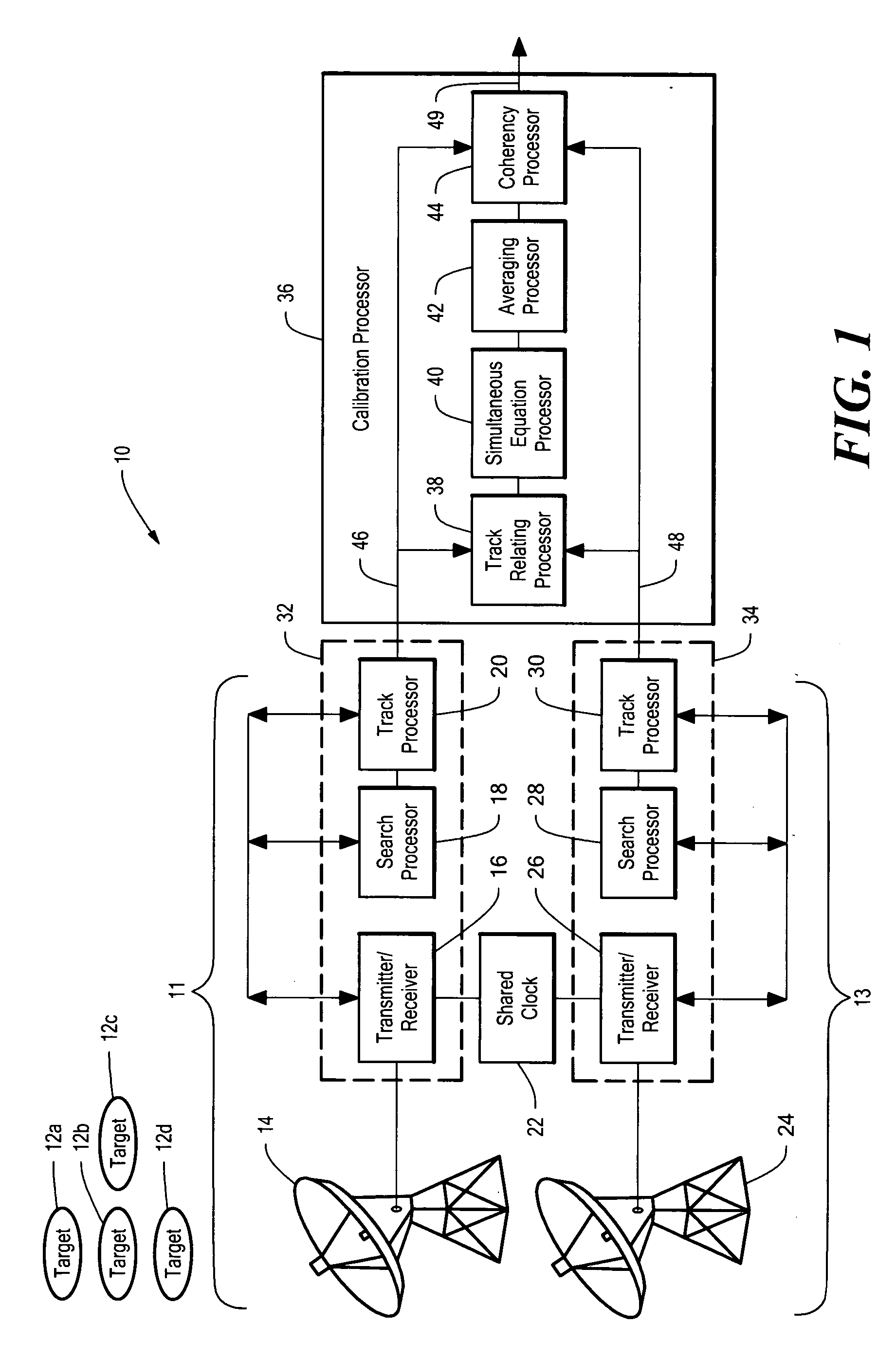
[0024] Referring now to FIG. 1, a system 10 for cohering two radar systems includes a first radar system 11, also referred to herein as a...


PUM


Abstract

A system and technique for calibrating a plurality of radars provides a set of simultaneous equations derived from monostatic echo returns from a plurality of targets. A solution of the simultaneous equations provides relative position calibration factors and time delay calibration factors associated with the plurality of radars. The relative position calibration factors and the time delay calibration factors allow the plurality of radars to be coherently combined with only a small amount of processing gain loss compared with an ideal coherent processing gain.

Description

CROSS REFERENCE TO RELATED APPLICATIONS [0001] Not Applicable. STATEMENT REGARDING FEDERALLY SPONSORED RESEARCH [0002] Not Applicable. FIELD OF THE INVENTION [0003] This invention relates generally to radar systems and methods, and, more particularly, to a system and technique for calibrating a plurality of radars to allow coherent processing. BACKGROUND OF THE INVENTION [0004] As is known, a single radar system having a radar antenna, also referred to herein as a radar array, has a theoretical maximum processing gain and signal to noise ratio, each of which directly affects the ability of a radar to detect and to track a target. The maximum processing gain and the maximum signal to noise ratio are determined by a variety of radio characteristics, including but not limited to, a radar antenna size, a radar transmit and receive beamwidth, a type of received signal processing, a radar transmit power, and a radar receiver noise. Each of these characteristics is substantially fixed for ...

Claims


Application Information

Patent Timeline
Patent Type & Authority Applications(United States)
IPC IPC(8): G01S7/40G01S13/66
CPCG01S7/4004G01S13/87G01S13/723G01S13/003G01S13/06
Inventor POZGAY, JEROME HOWARDDULL, WESLEY THOMAS
Owner RAYTHEON CO
Why Eureka
Try Eureka