
Image taking apparatus with flash device

a technology of flash device and image, which is applied in the field of image taking apparatus, can solve the problems of small light emission amount compared to the conventional xenon tube, and the possibility of leds being destroyed by high heating value, so as to prevent the destruction of leds, reduce the cost of parts, and effectively use

Inactive Publication Date: 2006-06-22
FUJIFILM CORP
View PDF20 Cites 43 Cited by
  • Summary
  • Abstract
  • Description
  • Claims
  • Application Information

AI Technical Summary

Benefits of technology

[0006] In view of the foregoing, an object of the present invention is to provide an image taking apparatus which prevents destruction of a light emitting diode (LED) used as a flash light source by heat.
[0010] In another preferred embodiment according to the present invention, the LED light source is attached to a front of the main body through the metal member. In another preferred embodiment according to the present invention, the LED light source is attached to the front face of the main body having the heat radiation effect. In another preferred embodiment according to the present invention, the LED light source is attached to the front end surface of the lens barrel having the heat radiation effect.
[0011] According to the present invention, since the LED light source is attached to the metal member having the heat radiation effect, the heat of the LED light source is radiated through the metal member even when a large amount of electric current which provides the sufficient light emission amount is supplied to each of the LEDs. Accordingly, the destruction of the LEDs is prevented. Further, since the metal member which mounts the LED light source is attached to the front end surface of the lens barrel, there is no vignetting of the flashlight caused by the lens barrel. As a result, the flash light is effectively used. Further, since the optical axes of the flash light and the photographic light are approximately parallel, it becomes possible to take almost shadowless images. When the metal member also serves as the ornament plate of the lens barrel, the parts cost is reduced.
[0012] It is also possible to directly attach the LED light source to the front end surface of the lens barrel having the heat radiation effect or to the front of the main body having the heat radiation effect. In that case, there is no vignetting caused by the lens barrel when the image taking apparatus has a short focus lens and the like in which the lens barrel does not considerably protrude from the front of the main body. As a result, the flash is effectively used.

Problems solved by technology

The LEDs described above have a disadvantage that the light emission amount is small compared to the conventional xenon tubes.
However, the LEDs may be destroyed by the high heating value.

Method used


Image

  • Image taking apparatus with flash device
  • Image taking apparatus with flash device
  • Image taking apparatus with flash device

Examples


Embodiment Construction

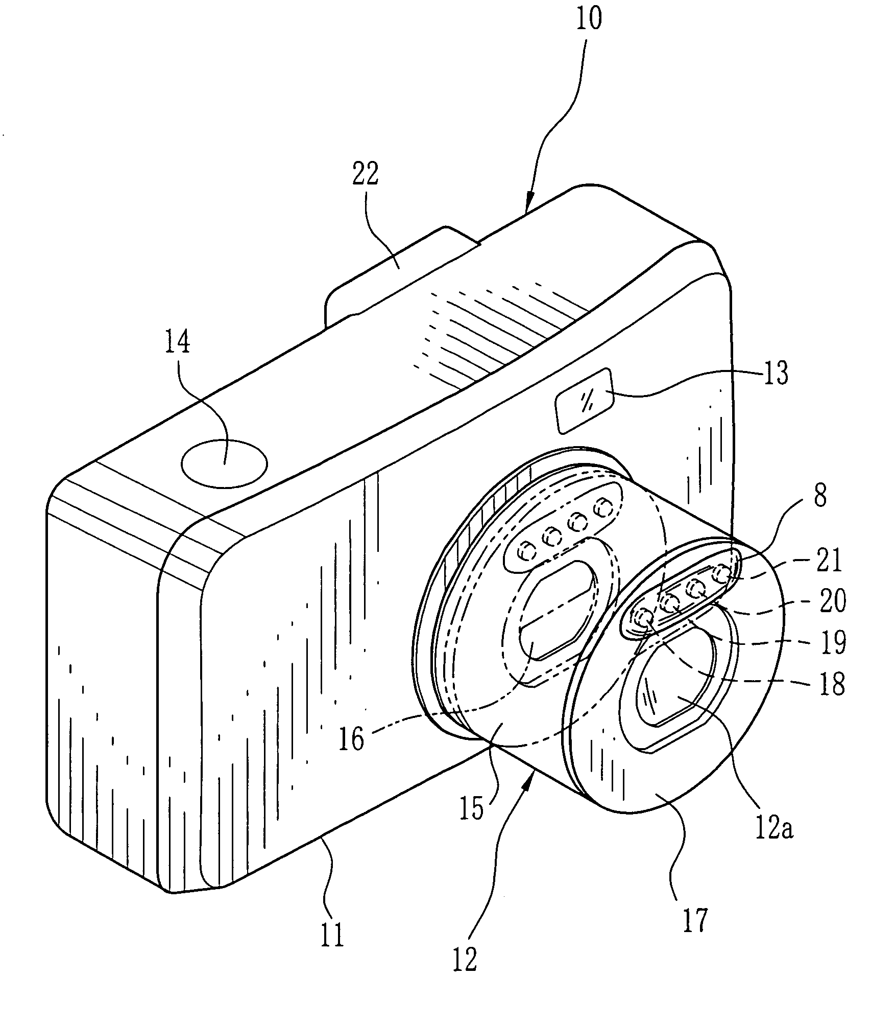
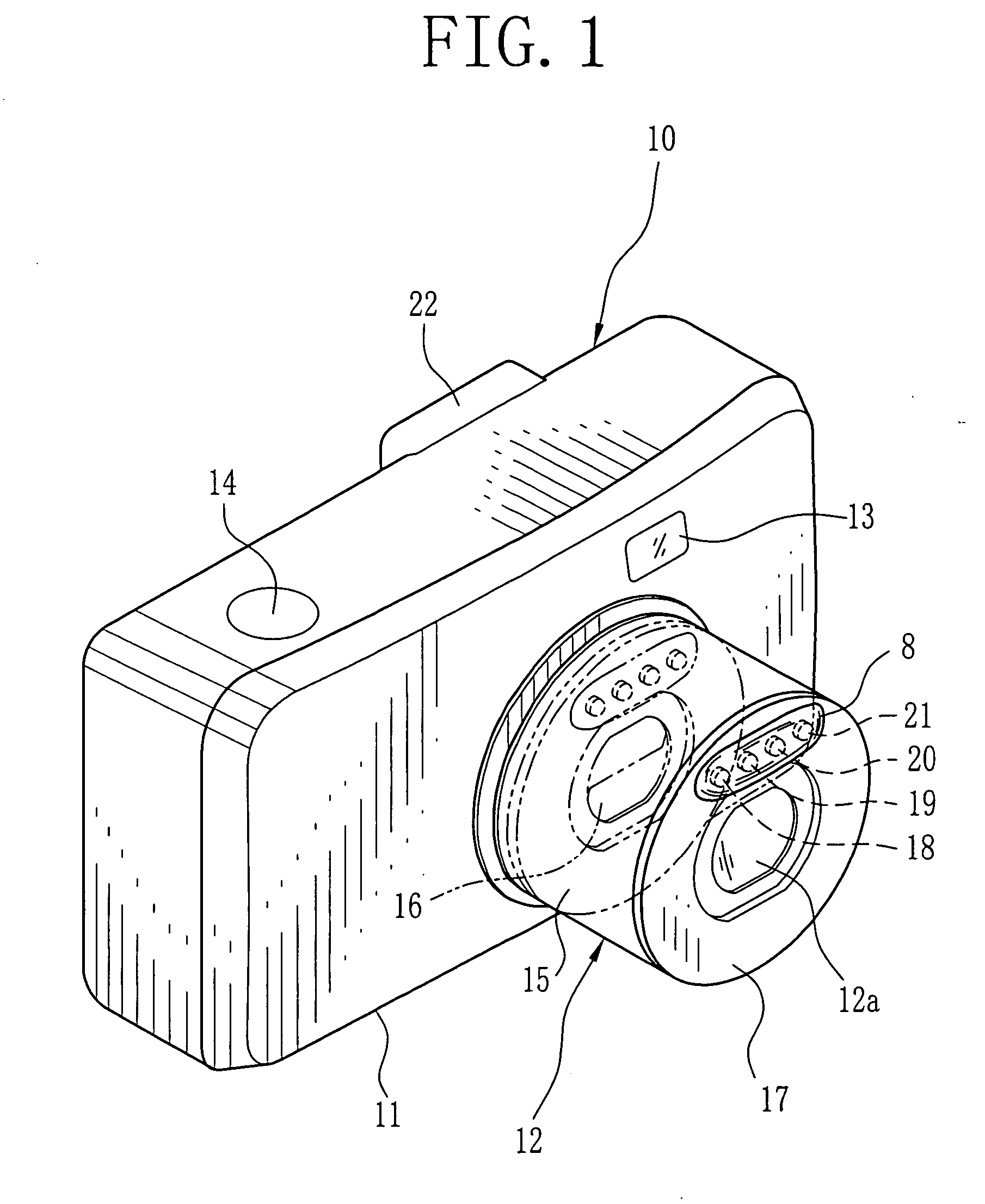
[0028] In FIG. 1, a digital camera 10 has a camera body (a main body) 11. On a front surface of the camera body 11, a taking lens 12 of a fixed-focus type and a front viewfinder window 13 are disposed. Further, on an upper surface of the camera body 11, a shutter button 14 is disposed. The taking lens 12 can be removably attached to the camera body 11.

[0029] A lens barrel 15 of the taking lens 12 is in a collapsed position as shown in a chain double-dashed line when the power is turned off. When the power is turned on, the lens barrel 15 is protruded to be ready for taking images. A lens barrier 16 is closed when the power is turned off or the lens barrel 15 is in the collapsed position. When the power is turned on, the lens barrier 16 is opened so that a lens system 12a is exposed.

[0030] The lens barrel 15 is formed of resin. A ring-like ornament plate 17 is attached to a front end surface (an end section on an object side) of the lens barrel 15 so as to cover the whole front end...


PUM


Abstract

An ornament plate of a ring-shape made of a metal with a high heat radiation effect, for instance, aluminum, is attached to an end surface on an object side of a lens barrel such that the ornament plate covers the whole front part of the lens barrel. Four kinds of LEDs of high luminance type constructing an LED light source are attached to the lens barrel through the ornament plate used as a substrate. A light diffusion cover made of a transparent resin is attached to the front of the ornament plate for covering the LEDs. When using the flash, a high voltage current is applied to the LEDs to emit flash light. Each LED generates heat. However, the heat is radiated through the ornament plate.

Description

BACKGROUND OF THE INVENTION [0001] 1. Field of the Invention The present invention relates to an image taking apparatus such as a digital camera, a mobile phone with a camera and the like using a light emitting diode as a flash light source of a flash device. [0002] 2. Background Arts Photographic film cameras, digital cameras, mobile phones with cameras and the like are known as image taking apparatuses. Many of the image taking apparatuses are equipped with flash devices so as to illuminate main subjects for taking beautiful pictures in low luminance conditions. [0003] Xenon (Xe) tubes have been used as flash light sources in the conventional flash devices. However, as for the digital camera, a flash device using a light emitting diode (an LED) is recently suggested in terms of low noise, easy downsizing, and low cost. [0004] For instance, an image taking apparatus with plural LEDs is known which can adjust the color balance of the flash light by sequentially emitting each LED at ...

Claims


Application Information

Patent Timeline
IPC IPC(8): G03B15/02
CPCG03B15/05H04N5/2354H04N9/735H04N2101/00G03B2215/0567G03B2215/0575G03B2215/0592H04N23/74H04N23/88
Inventor MAEDA, YUTAKA
Owner FUJIFILM CORP
Learn More