Light guide plate made of transparent resin, molding method thereof, insert block, mold assembly, and area light apparatus

a technology of transparent resin and light guide plate, which is applied in the field of transparent resin light guide plate, molding method thereof, insert block, mold assembly, and area light apparatus, can solve the problems of large number of steps for assembling, large number of prism sheets, and inability to form prism-shaped concave-convex portions in surface portions of light guide plates, etc., to achieve accurate and reliable formation of desired concave portions or convex portions, and accurate and reliable formation of desired conca

Inactive Publication Date: 2006-06-22
MITSUBISHI ENG PLASTICS CORP
View PDF17 Cites 9 Cited by
  • Summary
  • Abstract
  • Description
  • Claims
  • Application Information

AI Technical Summary

Benefits of technology

[0022] It is a first object of the present invention to provide a light guide plate (light guiding plate) that has desired concave portions or convex portions accurately and reliably formed in its surface and is made of a transparent resin and a molding method of a light guide plate, an insert block that permits accurate and reliable formation of desired concave portions or convex portions in the surface of a light guide plate (light guiding plate) made of a transparent resin, a mold assembly into which the above insert block is incorporated, and an area light apparatus (surface-emitting light source apparatus) into which the above light guide plate (light guiding plate) is incorporated.
[0023] It is a second object of the present invention to provide a mold assembly for use with an insert block, which can be relatively easily adjusted when the insert block is attached to a mold portion, which permits a decrease in fabrication cost of a mold assembly, which can reliably prevent damage or breakage of an end portion or an edge portion of the insert block, which is excellent in transfer of a cavity surface of the insert block to the surface of a light guide plate (light guiding plate), and which has durability against continuous operation of molding for a long period of time, in addition to the above first object.

Problems solved by technology

Meanwhile, a plurality of the prism sheets 355 have problems that they are expensive and that the number of steps for assembling them is large.
However, when the light guide plate 340 having the prism-shaped concavo-convex portion 342 in the surface is formed from a polycarbonate resin having poor flowability by an injection molding method, particularly, there is caused a problem that no prism-shaped concavo-convex portion can be formed in a surface portion of a light guide plate positioned far from a gate portion.
However, it is difficult to form a prism-shaped concavo-convex portion in zirconia ceramics, since the zirconia ceramics has high hardness and is fragile.
When an insert block is manufactured from zirconia ceramics and then the concavo-convex portion is mechanically formed in the surface of the insert block, it is difficult to form an intended shape or pattern.
Further, when the concavo-convex portion is mechanically formed in the surface concurrently with the formation of the insert block from zirconia ceramics, the insert block is liable to break due to a crack that occurs in the surface.
Particularly, the end portion of the insert block has a form weak in view of strength, so that there is caused a problem that when a stress is exerted on the end portion during assembling of a mold, the insert block is broken.
In a mold disclosed, for example, in JP-A-42650 / 1999, when a surface of an insert block and an insert-block-covering portion, facing such a surface of the insert block, have no sufficient high parallelism during clamping of the mold, there is a risk that the end portion of the insert block comes in contact with the insert-block-covering portion and, as a result, may be broken.
It is therefore difficult to cut zirconia ceramics with a general metal working machine.
Further, when it is cut (machined), the end portion of a cutting tool is liable to escape so that cutting is very difficult.
Further, when the insert block is constituted in a three-dimensional form, the problem is that metal machining of a mold portion near the insert-block-fitting portion is very difficult, so that it is required to rely on an ultra-precision working machine or a highly skilled worker.
Further, as the machining accuracy of the insert block increases, the production cost of the insert block increases, and further, the cost of the mold itself increases.
Moreover, when an insert block made of zirconia ceramics is fitted to a mold portion provided with the insert-block-covering portion, or when the insert block is fitted to a first mold member, the insert block may break if the fitting is not highly accurate.
A working machine for ceramics and a working machine for metal differ, and such a difference makes the fitting of the insert block difficult.
That is, it is difficult to cut an insert block made of ceramics with a surface cutting machine for metal.
However, the above machining is complicated.
Further, when the thickness of the adhesive is not uniform, the procedure of cutting the reverse surface of the metal plate for adjusting the height (or thickness) of the insert block is required to be carried out several times, so that the number of steps for manufacturing increases and increases a cost.
When the parallelism between the mold parting surface and the insert block is poor, there is caused a problem that the insert block may break in a worst case.
In these methods, however, it is difficult to form any metal layer having a thickness sufficient for cutting with a general cutting machine on the surface of the insert block.
Further, the cost of forming the metal layer is high, and another problem is that the adhesion of the metal layer to the surface of the insert block is not so high.
Since, however, general zirconia ceramics is electrically non-conductive as already described, it is impossible to form the metal layer by an electric plating method alone.
However, the concavo-convex portion has a relatively large height and has a large pitch of peaks and valleys, and further, the distance from the light source to the concavo-convex portion differs depending upon peaks and valley regions of the concavo-convex portion, so that non-uniformity in brightness is liable to occur, or light from the light source or light reflected by the reflection member can be not always fully utilized.
However, it is difficult to form fine peaks and valleys of the concavo-convex portion in the surface of the light-transmitting member by an injection molding method.
However, it cannot be said that the above measures are preferred in view of energy saving.

Method used


Image

  • Light guide plate made of transparent resin, molding method thereof, insert block, mold assembly, and area light apparatus
  • Light guide plate made of transparent resin, molding method thereof, insert block, mold assembly, and area light apparatus
  • Light guide plate made of transparent resin, molding method thereof, insert block, mold assembly, and area light apparatus

Examples


example 1

[0256] Example 1 is concerned with a light guide plate / area light apparatus according to the first / third aspects of the present invention, and an insert block / mold assembly / molding method according to the first / third aspects of the present invention. The insert block and the mold assembly in Example 1 are concerned with the insert block and the mold assembly having the first constitution of the present invention and further concerned with the second structure of the mold assembly, etc., of the present invention.

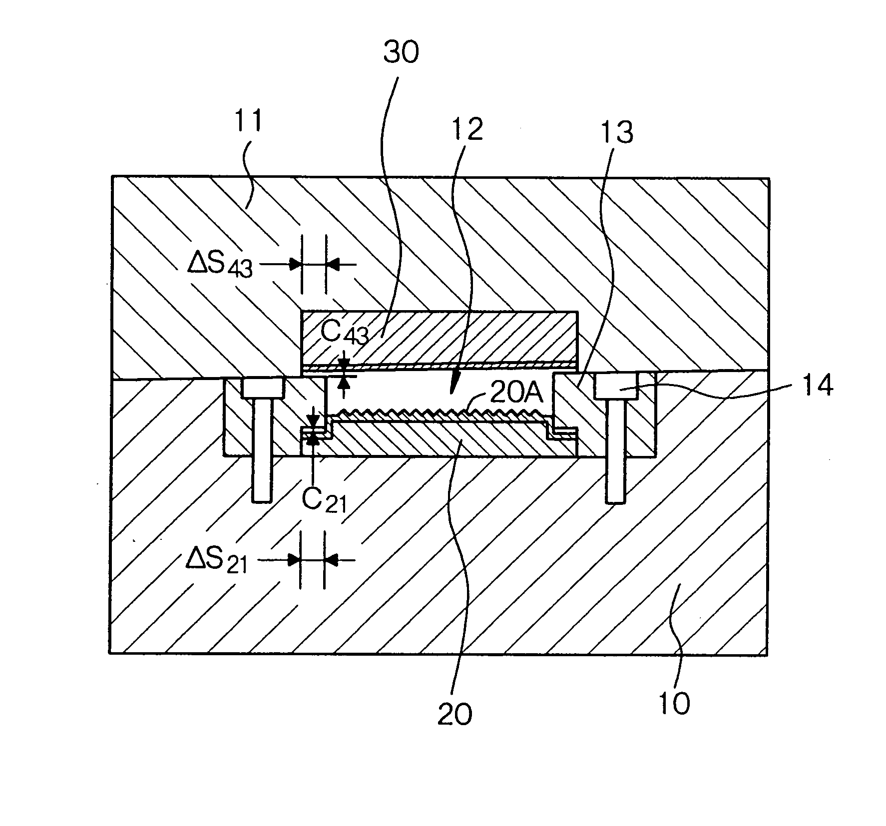
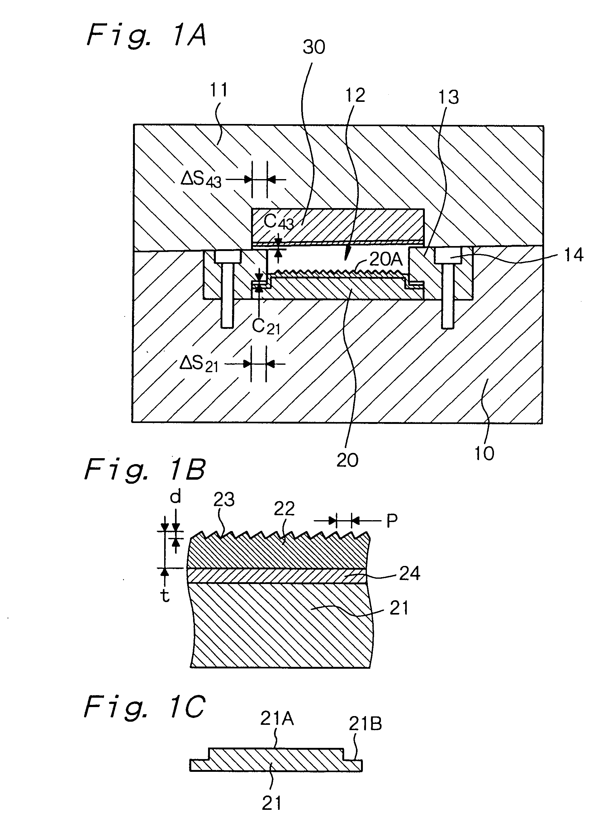
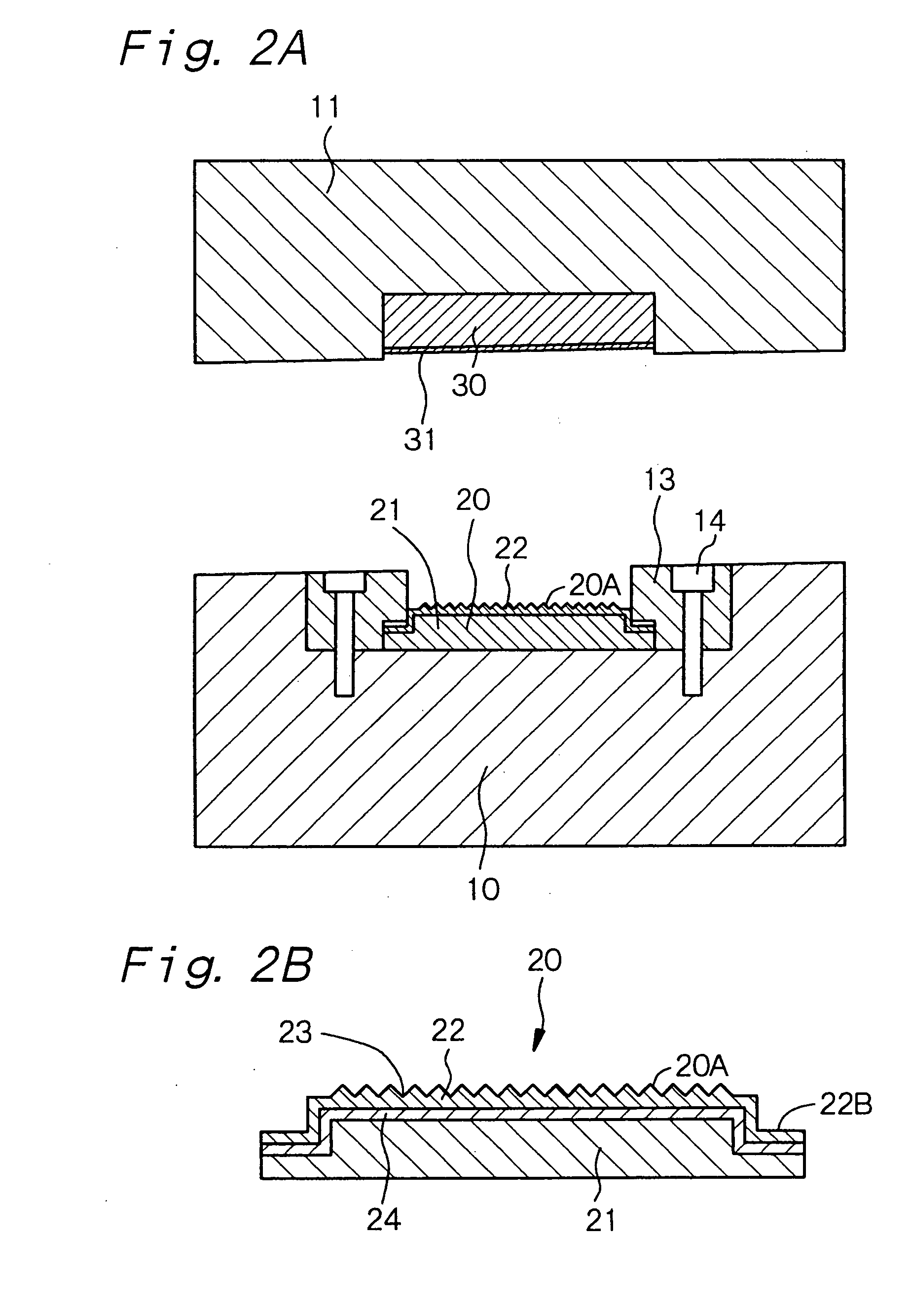
[0257]FIG. 1A and FIG. 2A show schematic cross-sectional views of the mold assembly in Example 1. The mold assembly has (A) a mold for forming a light guide plate made of a transparent resin, the mold comprising a first mold member (movable mold member) 10 and a second mold member (fixed mold member) 11 and in which a cavity 12 is formed when the mold is clamped, (B) a side-gate-type molten resin injection portion (not shown) provided for introducing a molten transparent res...

example 2

[0274] Example 2 is a variant of Example 1. An insert block 20 in Example 2 was fabricated by the following method. A second insert block 30 can be also fabricated by the same method.

[0275] First, a mixture of a zirconia powder and an yttrialite powder was press-molded and then calcined or sintered to prepare the insert block body 21. Then, that surface (surface 21A) of the insert block body 21 which faces the cavity 12 and that surface (surface 21B) which faces the cover plate 13 were subjected to blasting treatment using alumina particles, so that these surfaces 21A and 21B had a surface roughness Rz of 2 μm. Then, a 2 μm thick Ni—P layer was formed on the above surfaces 21A and 21B of the insert block body 21 by an electroless plating method, then, a 5 μm thick Ni layer was formed thereon by an electric plating method, and further, a 100 μm thick Ni—P layer was formed thereon by an electroless plating method. Then, the Ni—P layer was machined using a diamond tool having saw-blad...

example 3

[0279] Example 3 is also a variant of Example 1. Example 3 used partially stabilized electrically conductive zirconia ceramics to constitute an insert block body 21. Further, a metal layer 22 was formed on that surface 21A of the insert block body 21 which was to face the cavity. That is, specifically, the insert block 20 is made of partially stabilized zirconia (ZrO2—Y2O3) ceramics containing 8% by weight of Fe2O3 as an electrically conducting agent. Further, the content of Y2O3 as a partially stabilizing agent in the partially stabilized zirconia ceramics was 3 mol %. The above electrically conductive zirconia ceramics has a heat conductivity of approximately 3.8 J / (m·s·k) and a specific volume resistivity of 1×10⁸ Ω·cm. The metal layer 22 is made of chromium (Cr). In Example 3, the metal layer 22 was formed on the entire surface of the insert block 20 by an electric plating method.

[0280] Other elements of the insert block of Example 3 can be the same as those of the insert block...


PUM

PropertyMeasurementUnit
heightaaaaaaaaaa
heightaaaaaaaaaa
heightaaaaaaaaaa

Abstract

A light guide plate which is made of a transparent resin and has a first main surface and a second main surface opposite to said first main surface, said first main surface having a surface portion provided with convex portions having a height of 5×10⁻⁷ m to 6×10⁻⁵ m each and a pitch of 5×10⁻⁷ m to 4×10⁻⁴ m, each convex portion having a tip portion, and the convex portions of at least 80% of the total convex portions having the tip portions having a radius of curvature of 2×10⁻⁶ m or less.

Description

BACKGROUND OF THE INVENTION AND RELATED ART STATEMENT [0001] The present invention relates to a light guide plate (light guiding plate) made of a transparent resin for a liquid crystal display in a personal computer, a cellular phone, PDA (personal digital assistant) and the like or for use in other fields, a molding method of a light guide plate, an insert block suitable for molding the above light guide plate, a mold assembly having the insert block suitable for molding the above light guide plate, and an area light apparatus (surface-emitting light source apparatus) having such a light guide plate. [0002] A liquid crystal display for use in a personal computer, a cellular phone, PDA and the like has an area light apparatus incorporated to cope with demands of a decrease in thickness, a decrease in weight, power saving, higher brightness and higher definition of the liquid crystal display. The area light apparatus generally has a wedge-shaped light guide plate having tapered slant...

Claims


Application Information

Patent Timeline
Patent Type & Authority Applications(United States)
IPC IPC(8): F21V7/04B29C33/38G02B6/00B29C33/42B29C45/26B29C45/37B29D11/00B29L11/00F21V8/00G02B6/08G02B6/12G02F1/1335G02F1/13357
CPCB29C45/372B29D11/00663B29L2011/0075G02B6/0038G02B6/0046G02B6/005G02B6/0055G02B6/0065G02B6/0071G02B6/08G02B2006/12107Y10S425/81
Inventor TAHARA, HISASHIKANEISHI, AKIMASA
Owner MITSUBISHI ENG PLASTICS CORP
Why Eureka
Try Eureka