
Trunk network system for multipoint-to-multipoint relay

a trunk network and relay technology, applied in data switching networks, frequency-division multiplexes, instruments, etc., can solve the problems of affecting the reachability of packets that pass through the trunk network, communication is dropped, and packets are impeded

Active Publication Date: 2006-06-22
NEC CORP
View PDF5 Cites 18 Cited by
  • Summary
  • Abstract
  • Description
  • Claims
  • Application Information

AI Technical Summary

Benefits of technology

[0016] It is an object of the present invention to provide a trunk network in which an external device can detect a failure in the transmission route in a short time interval.
[0020] According to the present invention, the external connection ports of node devices are classified into groups in advance, and the external connection ports are monitored in the port state monitor unit of each node device. In this way, changes in the state of each group are detected, the change in the state of a group is reported to other nodes from the group state management unit of a node device that has detected a change in the state of a group, and the states of ports that belong to that group are changed in the group state management units of other node devices. As a result, an external device that is connected to a trunk network that is made up from node devices can learn the occurrence of a failure in a short time interval by means of the changes in states of ports. In addition, because state changes are reported in group units, when a change in state occurs in any port, state changes can be generated in only ports that relate to that port and notification then implemented to external devices.

Problems solved by technology

In such a case, however, communication is dropped during the time interval from the occurrence of the failure until the completion of switching.
If a failure should occur in this type of trunk network, the reachability of packets that pass through the trunk network can no longer be guaranteed.
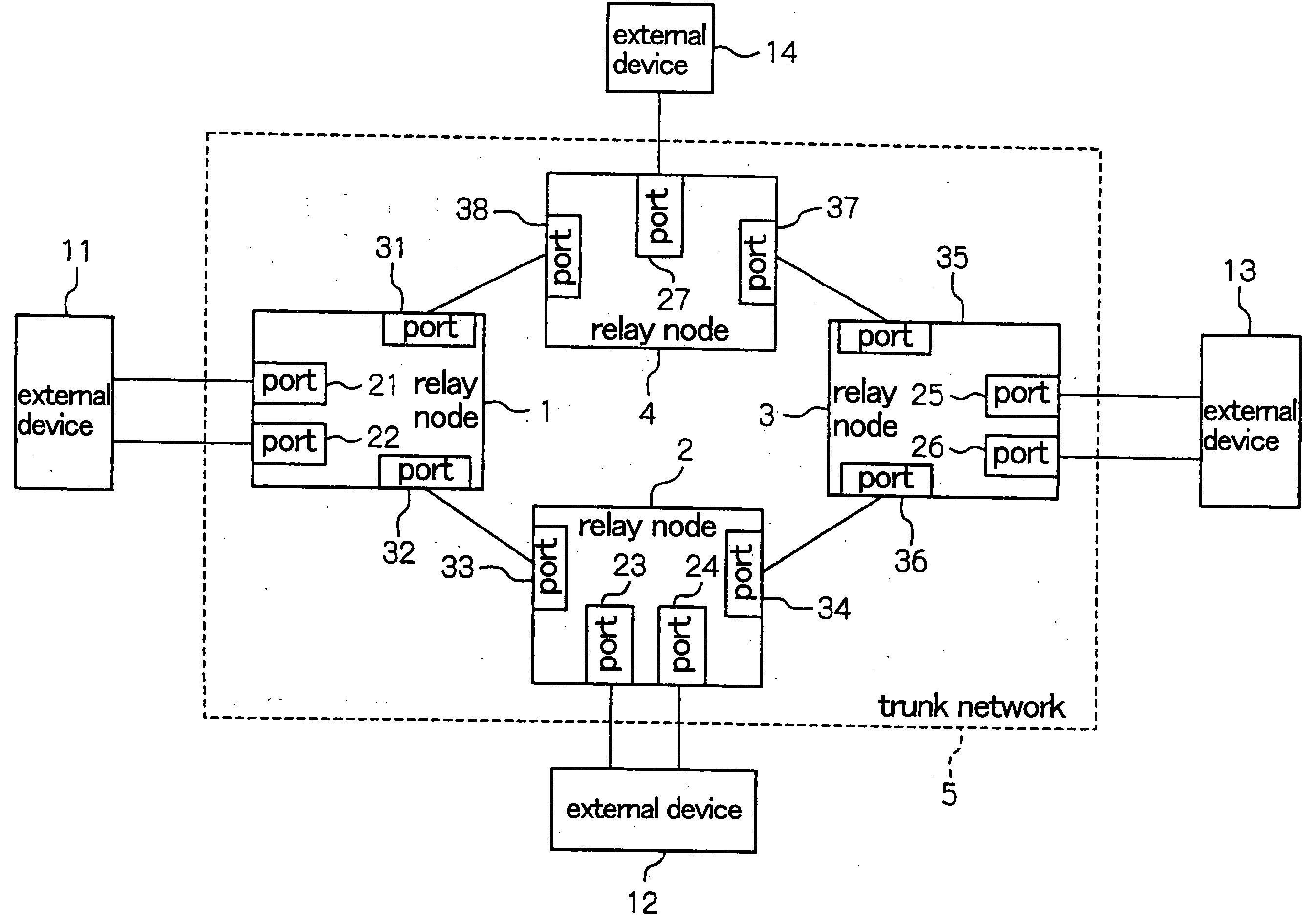
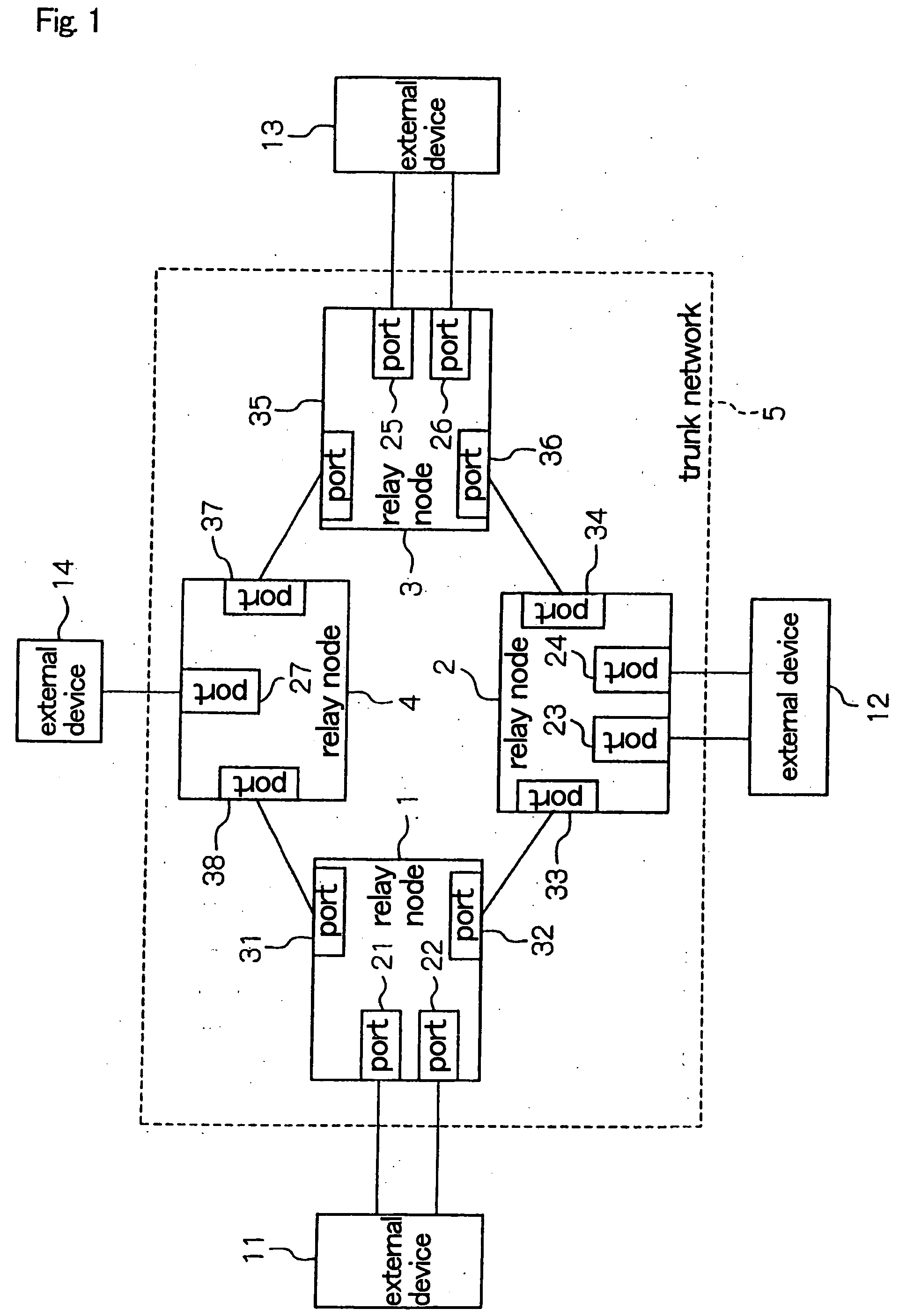
Examples of failures that would impede the reachability of packets include the failure of an external device, the failure of a port of a relay node that connects with an external device, or the failure of a relay node.
By comparison, an external device that is not directly connected with the site of a failure cannot directly detect the failure.
However, the above-described background art has the following problems:
This inability comes as a result of the lack of a one-to-one correspondence between links in a trunk network that provides multipoint-to-multipoint connection.
In other words, when the disconnection of a particular link is detected, determining which other link is to be disconnected is problematic because various connections are possible between links in a multipoint trunk network.
This method, however, generally entails a long time interval for detecting a failure.
Shortening the period for transmitting control packets can shorten the failure detection time interval.
However, shortening the period for transmitting control packets tends to increase the processing load in external devices or place pressure on the communication bandwidth of the transmission line.
Consequently, there is typically a limit to shortening the transmission period of the control packets, and adequately shortening the route switching time is therefore problematic.
As a result, during the long time interval from the occurrence of a failure until completion of switching, the external device continues to transmit packets to the route in which reachability has been impeded, lengthening the time interval in which communication is dropped.

Method used


Image

  • Trunk network system for multipoint-to-multipoint relay
  • Trunk network system for multipoint-to-multipoint relay
  • Trunk network system for multipoint-to-multipoint relay

Examples


first embodiment

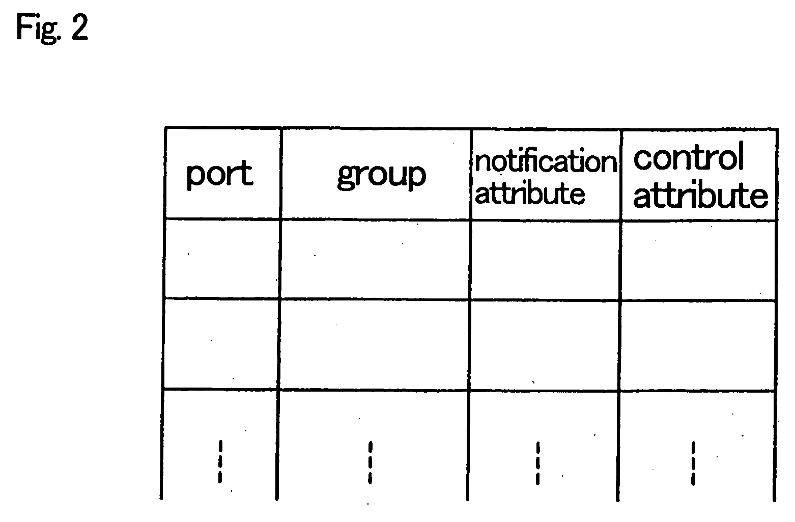
[0041]FIG. 2 is a table showing the attributes that are set in the external connection ports of a relay node according to the Referring to FIG. 2, the group, notification attribute, and control attribute are set in each port.

[0042] The external connection ports of each relay node are classified into groups by means of the settings. The method of determining these groups is open to variation, but according to one method that can be considered, settings may be made such that groups are composed of ports that will be affected by the occurrence of a failure in any port within the group. According to another method that can be considered, ports that are included in the same set of a redundant composition may be classified in the same group.

[0043] The notification attribute is attribute information that indicates whether, when a failure occurs at that port, the failure of the group is to be notified to other relay nodes, this attribute being set to “ON” or “OFF.” The “ON” setting of fai...

second embodiment

[0094] Explanation next regards the present invention.

[0095] In the second embodiment, a configuration is shown as an ideal example in which a server and client devices (hereinbelow referred to as “clients”) are connected as external devices to relay nodes.

[0096]FIG. 11 is a block diagram showing the configuration of the trunk network according to the second embodiment. Referring to FIG. 11, trunk network 10 includes relay nodes 6-9.

[0097] Relay node 6 includes external connection port 61 and node connection ports 71 and 72. Port 61 is connected to client 17. Relay node 7 includes external connection port 62 and node connection ports 73 and 74. Port 62 is connected to client 18. Relay node 8 includes external connection ports 63 and 64 and node connection ports 75 and 76. Port 64 is connected to server 16 and port 63 is connected to client 19. Relay node 9 includes external connection port 65 and node connection ports 77 and 78. Port 65 is connected to server 15.

[0098] Port 72 of...


PUM


Abstract

In a trunk network, each node, when notified from another node of a change in the state of a group to which external connection ports belong, changes the states of the external connection ports to cause external devices to detect the failure of the transmission route. A port state monitor unit classifies external connection ports into groups in advance and stores the correspondence of the external connection ports and the groups. The port state monitor unit then detects changes in the states of external connection ports. When a change of the state of any external connection port is detected in the port state monitor unit, a group state management unit reports state information that includes the states of groups that correspond to the external connection port to other nodes that make up the trunk network. Upon receiving state information from any other node, the group state management unit, in accordance with the states of groups that are included in the state information, changes the states of external connection ports that belong to these groups.

Description

BACKGROUND OF THE INVENTION [0001] 1. Field of the Invention [0002] The present invention relates to a trunk network for realizing multipoint-to-multipoint relay, and more particularly to the notification of failures in a trunk network. [0003] 2. Description of the Related Art [0004] Networks exist that are provided with alternate routes for improving reliability against failures. In the event of a failure on a transmission route in a network that is provided with alternate routes, the transmission of packets can be continued by switching to an alternate route. In such a case, however, communication is dropped during the time interval from the occurrence of the failure until the completion of switching. [0005] As a result, shortening the time interval from the occurrence of the failure until switching is completed (hereinbelow referred to as the “route switching time interval”) both obtains a corresponding shortening of the time interval in which communication is dropped and an impr...

Claims


Application Information

Patent Timeline
IPC IPC(8): H04J1/16H04L69/40H04L12/28
CPCH04L41/0677H04L41/0893H04L41/12H04L43/0805H04L43/0811H04L43/0817H04L45/22H04L45/28H04L49/55H04L69/40
Inventor YAMAUCHI, TOSHIRO
Owner NEC CORP
Learn More