Loudspeaker with integrated spider standoff ring

a technology of standoff ring and loudspeaker, which is applied in the direction of transducer details, electrical transducers, electrical apparatus, etc., can solve the problems of limiting the overall extent of excursion permitted, significant damage to the speaker, and the spiders provided by manufacturers for loudspeaker assembly may not be fla

Active Publication Date: 2006-06-22
JL AUDIO
View PDF16 Cites 18 Cited by
  • Summary
  • Abstract
  • Description
  • Claims
  • Application Information

AI Technical Summary

Benefits of technology

[0011] This invention is directed to a loudspeaker in which the foot of the spider is over molded with an annular plastic ring or standoff in an injection molding tool so that the spider and standoff form an integral unit. The standoff, in turn, is glued or otherwise affixed to the frame of the speaker to provide accurate centering of the voice coil relative to the magnetic gap of the motor structure.
[0012] This invention is predicated on the concept of ensuring that the outer diameter of the spider is flat and can be securely mounted to the speaker frame. As noted above, the spider foot is over molded with a plastic ring or standoff to form an integral unit. During the molding operation, the spider is clamped in a flat position by an injection molding tool to ensure its dimensional and geometric integrity. This molding operation further provides for precise concentricity of the standoff and spider. The standoff can then be glued or otherwise affixed to the frame to obtain a secure connection at that joint, and to accurately locate the spider so that the voice coil is centered relative to the magnetic gap of the motor structure of the speaker.
[0015] The use of a plastic ring or standoff to secure the spider foot allows for flexibility in the type of frame which can be used. Typically, speaker frames have a continuous spider plateau or seat which supports and connects to the spider foot. With the standoff of this invention, a frame having spaced arms may be employed with each arm being formed with a hole to receive a screw for attachment to the standoff as noted above. Alternatively, the standoff may be glued to the frame arms.

Problems solved by technology

If the voice coil deviates appreciably from its axial path within the magnetic gap, the voice coil can contact the pole piece or top plate of the motor structure causing significant damage to the speaker.
During excursion of the voice coil, the spider “tightens up” or stretches to an outer limit of displacement thus limiting the overall extent of excursion permitted and protecting the moving assembly from contacting other parts of the loudspeaker.
For various reasons, but most often as a result of shipping and handling, the spiders which are provided by manufacturers for assembly in loudspeakers may not be flat.
This geometric deformation of the spider foot not only compromises performance of the spider, but it can adversely affect the glue joint between the spider foot and frame.
The problem of attaching a geometrically deformed spider foot to the speaker frame cannot be satisfactorily overcome by merely pressing the foot down onto the frame during assembly.
However, the glue bead itself can create geometrically uneven areas along the spider foot, particularly if the glue bead is applied unevenly to the frame.
Another problem with prior art speakers involves failure of the joint connection between the spider foot and frame.
Since the spider is made of a cloth-like material, this glue joint is susceptible to “peel.” Starting at the inner diameter of the frame glue joint, it has been found that the spider can gradually peel away from the surface of the frame particularly in high excursion speakers such as subwoofers.

Method used


Image

  • Loudspeaker with integrated spider standoff ring
  • Loudspeaker with integrated spider standoff ring
  • Loudspeaker with integrated spider standoff ring

Examples


Embodiment Construction

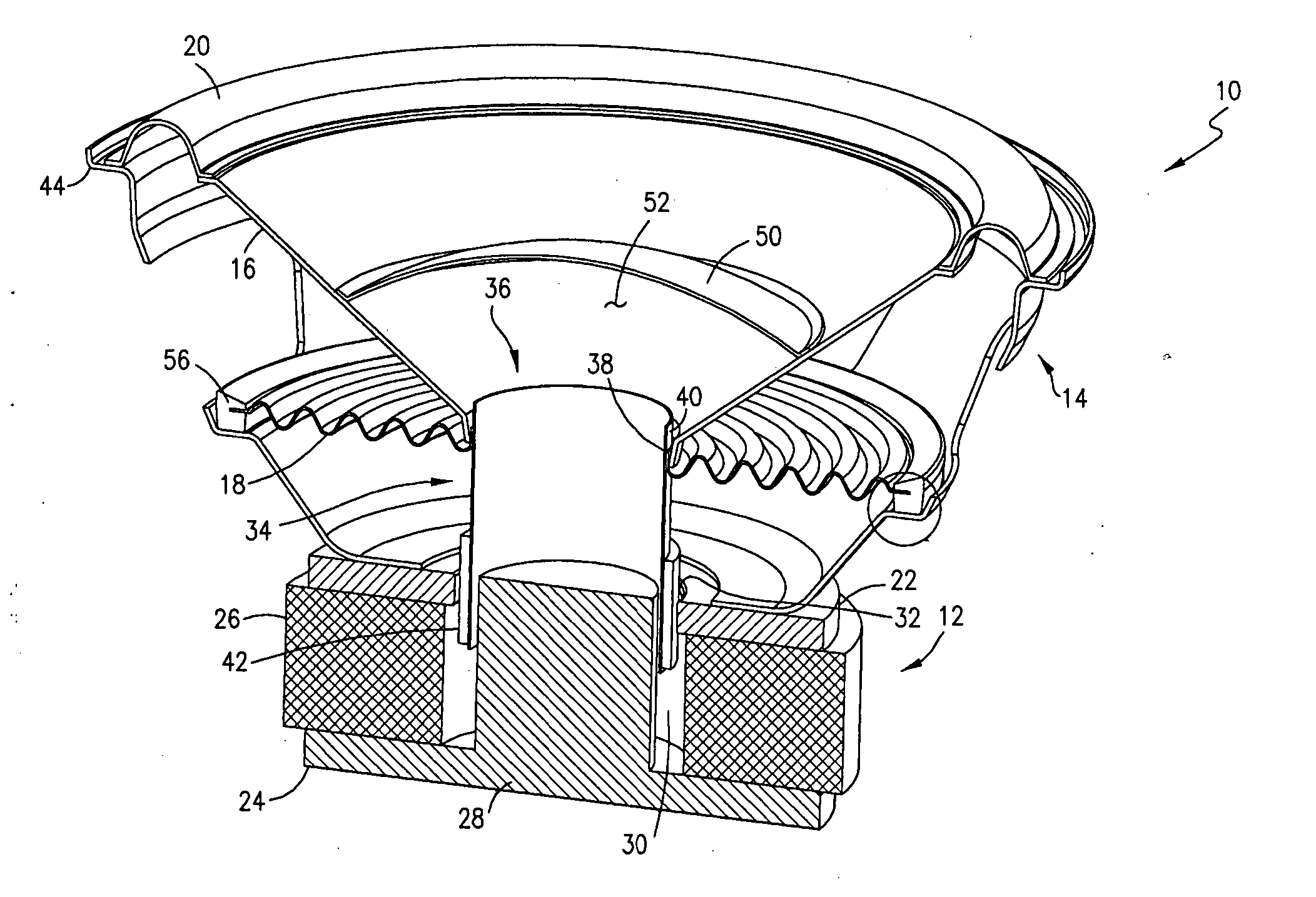
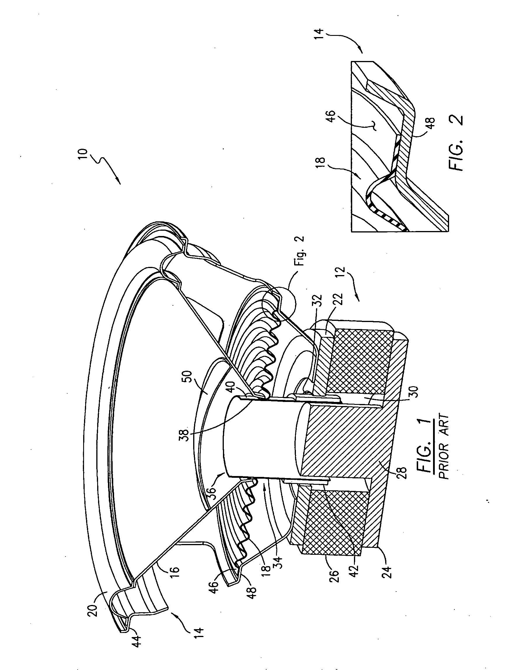
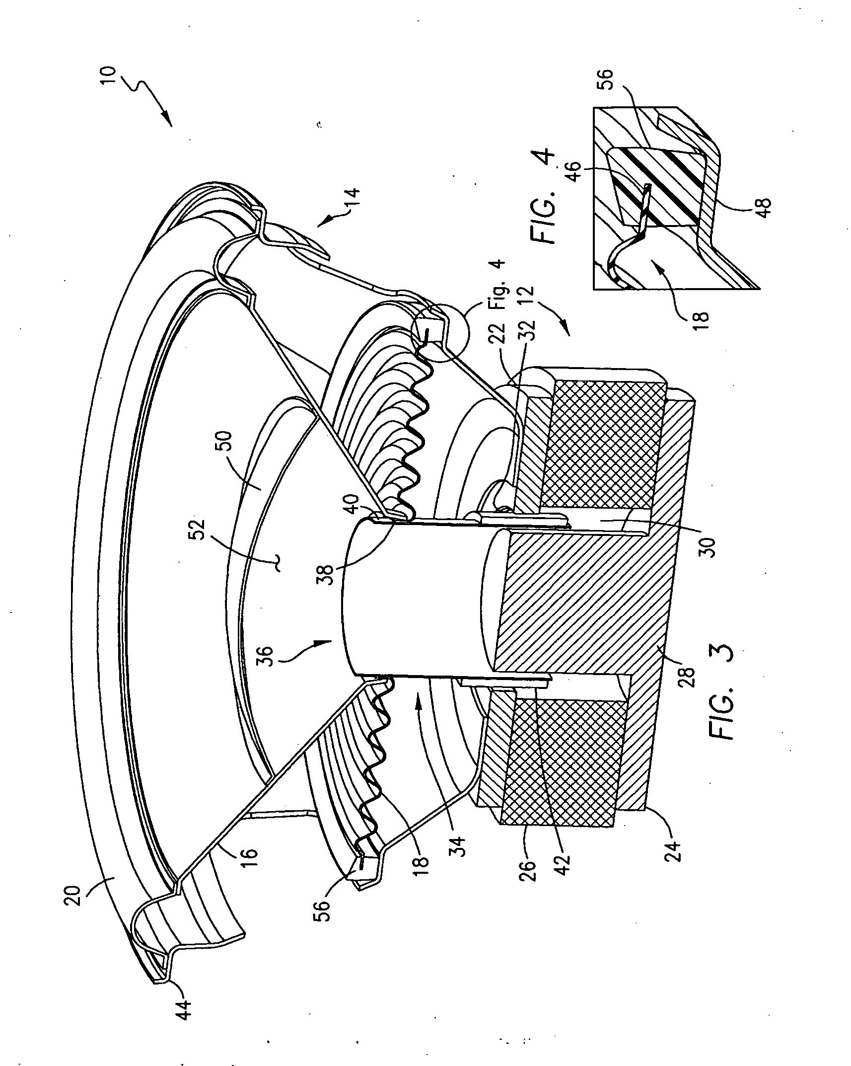
[0032] Referring initially to FIGS. 1 through 4, a loudspeaker 10 is illustrated which, in FIG. 1, includes a standard, prior art connection between the spider and frame, as described below, and in FIG. 3 an improved means of connecting the spider to the frame according to the present invention.

[0033] The speaker 10 generally comprises a motor structure 12, a frame 14 mounted to the motor structure 12, a diaphragm 16, a lower suspension or spider 18 and an upper suspension or surround 20. Conventionally, the motor structure 12 includes a top plate 22 and a back plate 24 which are spaced from one another and mount a permanent magnet 26 between them. A pole piece 28 is integrally formed with and extends upwardly from the back plate 24 into a central bore 30 formed in both the magnet 26 and top plate 22. A magnetic gap 32 is formed between the top plate 22 and the pole piece 28. A voice coil 34 is also provided which includes a hollow, cylindrical-shaped former 36 having an inner surf...


PUM


Abstract

A loudspeaker is provided in which the outer diameter or foot of the spider is over molded with a standoff formed of a plastic material in an injection molding tool so that the spider and standoff form an integral unit. The standoff, in turn, is glued or otherwise affixed to the frame of the speaker to provide accurate centering of the voice coil relative to the magnetic gap of the motor structure.

Description

FIELD OF THE INVENTION [0001] This invention relates to loudspeakers, and, more particularly, to a loudspeaker in which the outer periphery of the lower suspension is integrally molded with a plastic ring or standoff, which, in turn, is mounted to the frame of the speaker. BACKGROUND OF THE INVENTION [0002] Loudspeakers generally comprise a frame, a motor structure, a diaphragm, a lower suspension or spider and a surround or upper suspension. In one type of speaker, the motor structure includes a permanent magnet sandwiched between a top plate and a back plate, with a pole piece centrally mounted on the back plate so that both the top plate and magnet are concentrically disposed about the pole piece. A magnetic gap is formed between the pole piece and top plate within which a voice coil is axially movable. Preferably, the voice coil consists of a hollow, cylindrical-shaped former having an inner surface and an outer surface which mounts a winding of wire. [0003] The voice coil is mo...

Claims


Application Information

Patent Timeline
Patent Type & Authority Applications(United States)
IPC IPC(8): H04R1/00H04R9/06
CPCH04R7/22H04R9/043H04R9/06
Inventor PRONI, LUCIO
Owner JL AUDIO
Why Eureka
Try Eureka