
Optical polarity modules and systems

a technology of optical polarity and modules, applied in the field of fiber optic cables, can solve problems such as system problems, and the reflectance performance of flat polished ferrules in connectors is not sufficient for certain applications

Active Publication Date: 2006-06-22
CORNING OPTICAL COMM LLC
View PDF3 Cites 84 Cited by
  • Summary
  • Abstract
  • Description
  • Claims
  • Application Information

AI Technical Summary

Benefits of technology

[0008] In another aspect, the invention provides for an optical interconnection module that includes an enclosure defining at least two walls, an optical interconnection section formed in one of the at least two walls of the enclosure, the optical interconnection section having a first multi-fiber connector with a plurality of optical fibers extending therefrom, the multi-fiber connector having an orientation key, an optical connector station formed in the other of the at least two walls of the enclosure, the optical connector station having a plurality of optical fiber connectors, and the first multi-fiber connector and the plurality of optical fiber connectors being optically interconnected by the optical fibers extending from the first multi-fiber connector disposed in the enclosure, at least two optical fibers connected to the multi-fiber connector adjacent one other are connected to optical fiber connectors in the optical connector station are not immediately adjacent one another, and wherein a connection of the multi-fiber connector to another multi-fiber connector has a reflective performance of about ≦−65 dB.

Problems solved by technology

System problems can occur when the MTP assembly is used in an interconnect construction.
Additionally, the reflectance performance of flat polished ferrules in the connectors is not sufficient for certain applications.

Method used


Image

  • Optical polarity modules and systems
  • Optical polarity modules and systems
  • Optical polarity modules and systems

Examples


Embodiment Construction

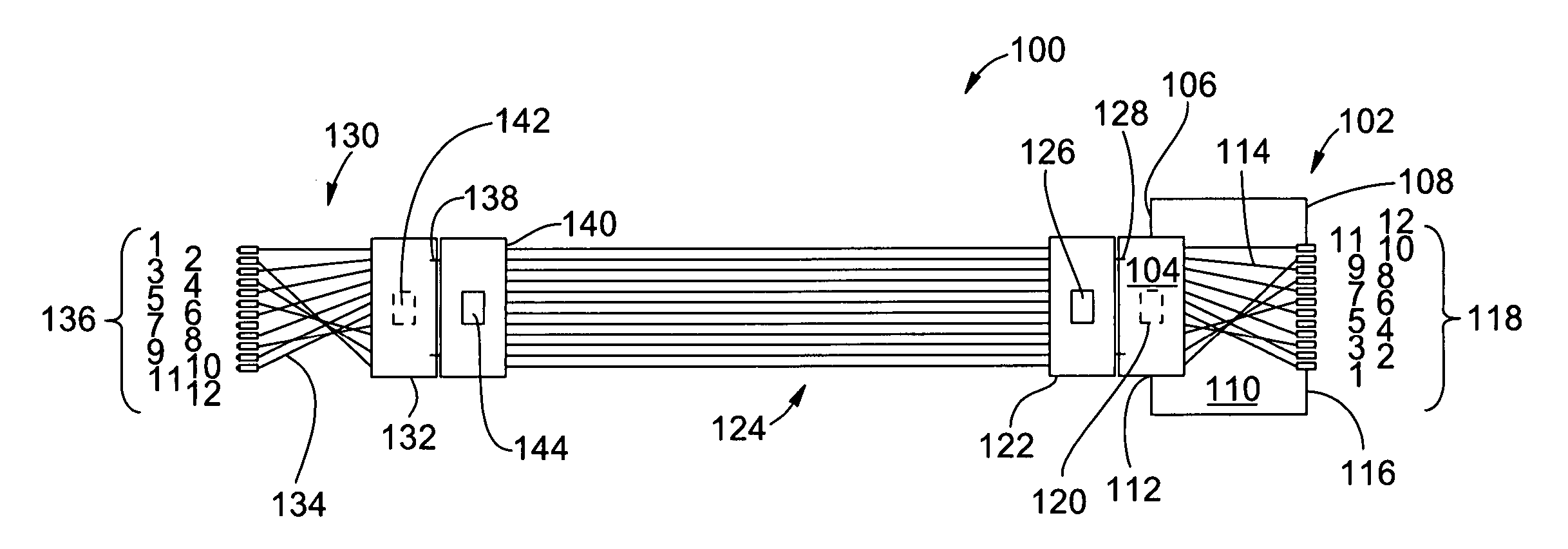
[0017] An embodiment of a system 100 that includes a module 102 according to the present invention is illustrated in FIG. 3. The module 102 can be used an optical networking module for use with an optical fiber ribbon, for example having twelve optical fibers, connected to, for example, an MTP or MPO optical connector 104. The module 102 preferably has at least two walls 106,108 to define a cavity 110, but may also have four walls to enclose the cavity 110. The module 102 preferably has an optical connection section 112 in one of the walls that includes the optical connector 104. The preferred, exemplary connector is an MTP or MPO connector 104. Connectors 104 are epoxy and polish compatible multi-fiber connectors, for example, a part of Corning Cable Systems' LANScape (Registered Trademark) solution set. The exemplary epoxy and polish connector is a twelve-fiber connector achieving very high density in a small space. The connector 104, as is known in the art, may have an end face t...


PUM


Abstract

A module and harness are described that allow for connectors in each to be mated with other connectors in a key up to key down orientation. The module and harness may also be a part of a larger optical assembly. The optical fibers in the module and harness connect a multi-fiber ferrule on one end with a plurality of connectors on the other end, at least some of adjacent optical fibers extending from the multi-fiber ferrule are not connected with adjacent connectors at the other end.

Description

[0001] The present invention relates to optical fiber interconnection modules, for example, to interconnection modules for use in a local area network (LAN). BACKGROUND OF THE INVENTIONS [0002] Conventional fiber optic cables comprise optical fibers that conduct light to transmit voice, video, and data information. An optical ribbon includes a group of optical fibers that are coated with a ribbon common layer, which may be of the ultraviolet (UV) light curable type. Typically, such a ribbon common layer is extruded about a group of individually colored optical fibers that have been arranged in a planar array, and is then irradiated with a UV light source that cures the ribbon common layer. The cured ribbon common layer protects the optical fibers and generally aligns the respective positions of optical fibers in the planar array. Optical fiber ribbons can be connected to multi-fiber connectors, for example, MTP connectors. MTP connectors can be used in LAN applications, for example,...

Claims


Application Information

Patent Timeline
Patent Type & Authority Applications(United States)
IPC IPC(8): G02B6/38G02B6/36
CPCG02B6/3851G02B6/3878G02B6/4472
Inventor SULLIVAN, KEITH D.
Owner CORNING OPTICAL COMM LLC
Features
  • Generate Ideas
  • Intellectual Property
  • Life Sciences
  • Materials
  • Tech Scout
  • Unparalleled Data Quality
  • Higher Quality Content
  • 60% Fewer Hallucinations
Learn More