
Flash spun web containing sub-micron filaments and process for forming same

a technology of flash spinning and filaments, which is applied in the field of flash spinning webs, can solve the problems of less comfortable clothing, less air flow resistance, and barrier at the expense of breathability

Inactive Publication Date: 2006-06-22
EI DU PONT DE NEMOURS & CO
View PDF24 Cites 74 Cited by
  • Summary
  • Abstract
  • Description
  • Claims
  • Application Information

AI Technical Summary

Benefits of technology

[0015] A first embodiment of the present invention is a nonwoven fibrous structure comprising an interconnecting web of polyolefin filaments having filament widths greater than about 1 micrometer which are further interconnected with webs of smaller polyolefin filaments having filament widths less than about 1 micrometer, wherein said smaller polyolefin filaments comprise a majority of all filaments.
[0016] A second embodiment of the present invention is a nonwoven fibrous structure comprising a collection of filaments formed from a polyolefin composition wherein the mean of the filament widths is less than about 1 micrometer and the maximum of the filament widths is greater than about 1 micrometer.
[0017] A third embodiment of the present invention is a nonwoven fibrous structure comprising a collection of filaments formed from a polyolefin composition comprising a collection of polyolefin filaments wherein the mean of the filament widths is less than about 1 micrometer, and pores formed between said polyolefin filaments, said nonwoven fibrous structure exhibiting a pore size diameter equivalent distribution of between about 0.20 to

Problems solved by technology

Unfortunately, smaller pore size also generally results in higher air flow resistance and a less comfortable garment.
However, this barrier is at the expense of breathability, rendering fabrics containing such films uncomfortable for the wearer.
In addition, since the microporous film itself is usually not very durable or cloth-like, it is typically laminated to at least one nonwoven layer or preferably two layers, forming a sandwich with the film in the middle.
This construction adds additional weight and expensive processing steps.
As with the microporous films, this construction adds additional weight for the garment's wearer and expensive process steps for the manufacturer.
However, the flash spinning processes developed to date do not produce fibrous webs having significant quantities of sub-micron filaments.
However, like the other laminated structures, nanofibers typically need supporting layers.
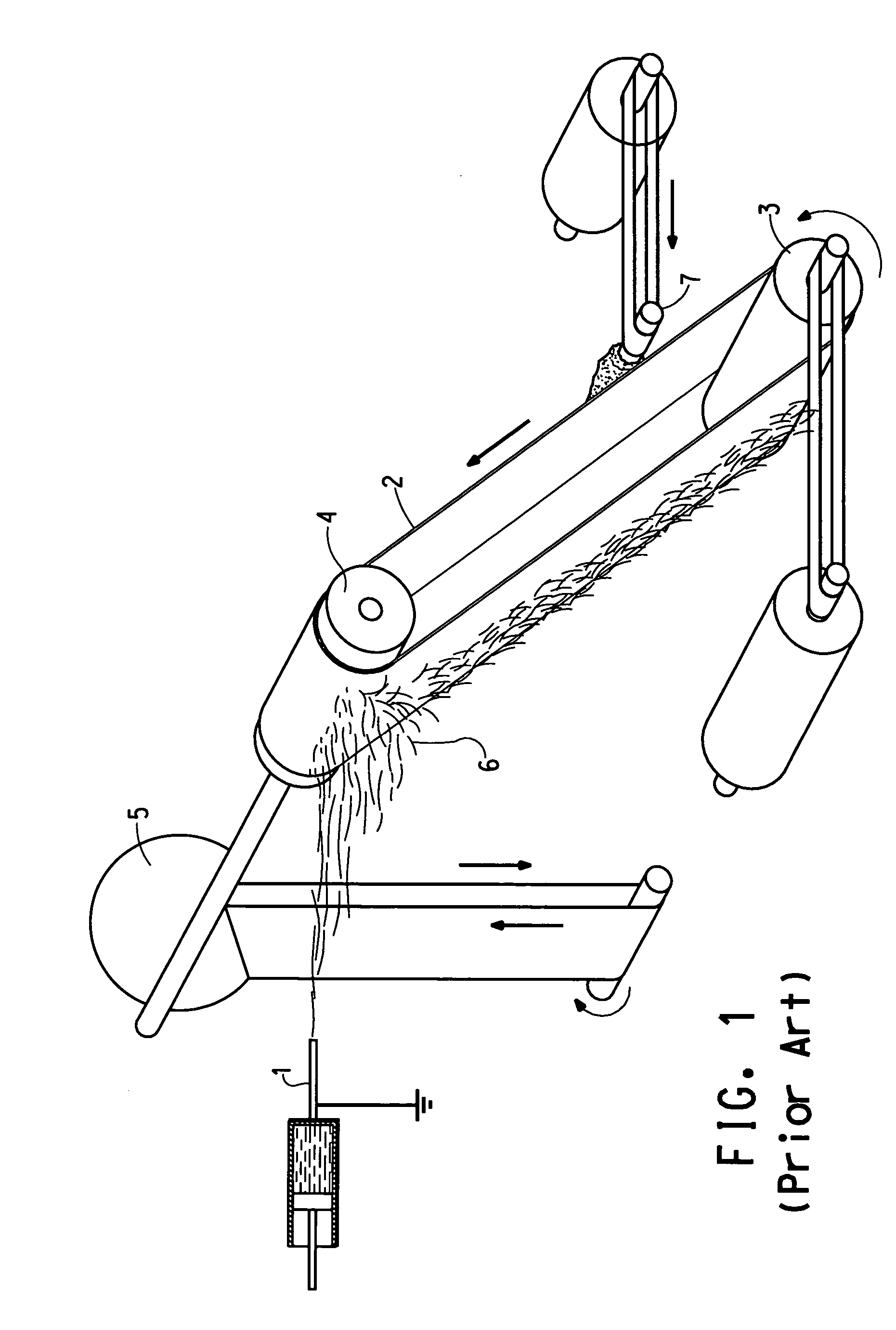
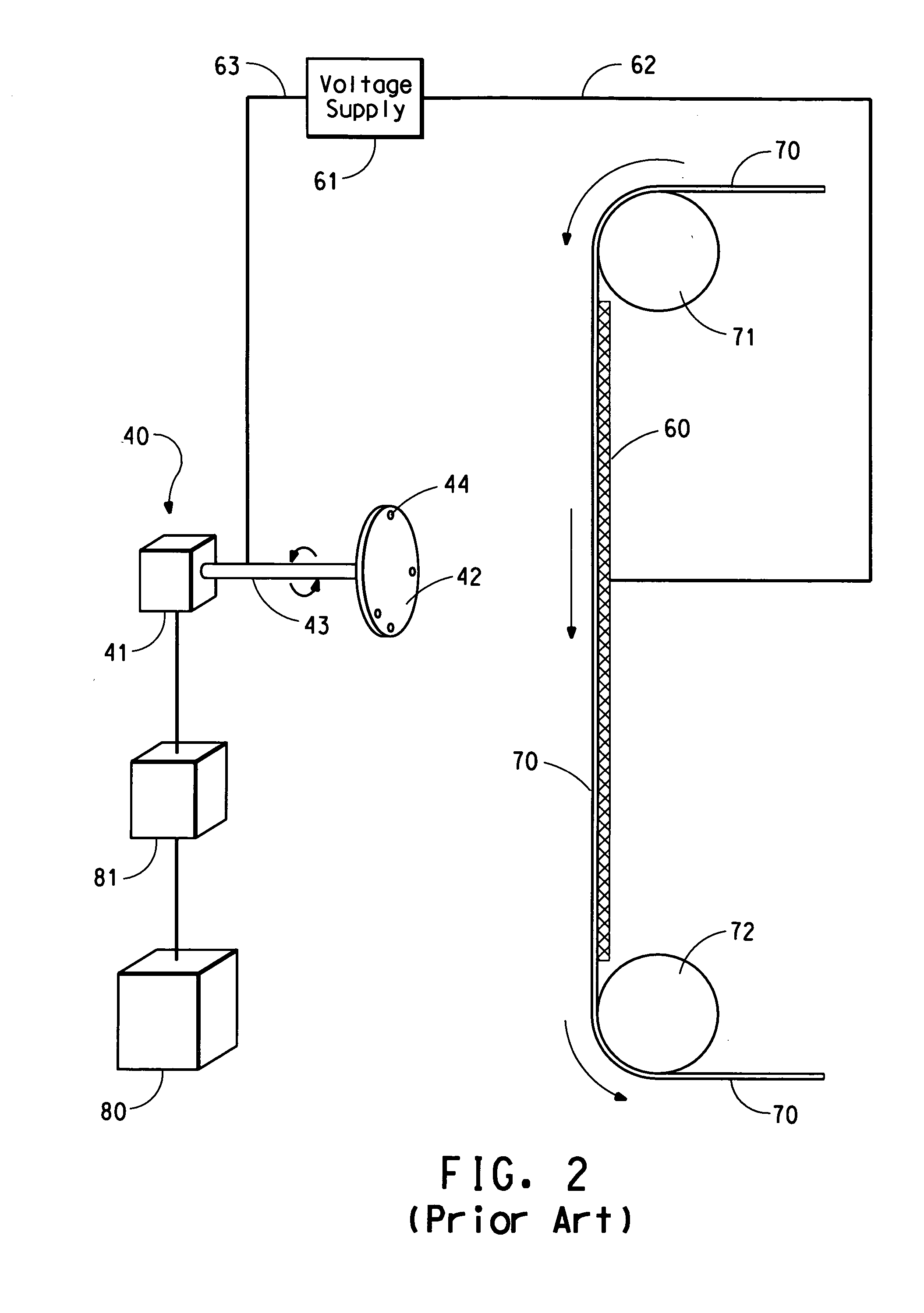
A major problem with this technique is low flow rate, on the order of 0.1 gram of polymer solution / minute / hole, far too low for industrial applications.
This limitation is due to the coupling of the electric field and the flow rate.
There are two other limitations of classical electrospinning technology that involve the nature of the polymer.
The second polymer-based limitation of classical electrospinning involves polymer solubility in the solvent.
This apparent requirement severely limits the polymers suitable for being spun into nanofibers.

Method used


Image

  • Flash spun web containing sub-micron filaments and process for forming same
  • Flash spun web containing sub-micron filaments and process for forming same
  • Flash spun web containing sub-micron filaments and process for forming same

Examples


example 1

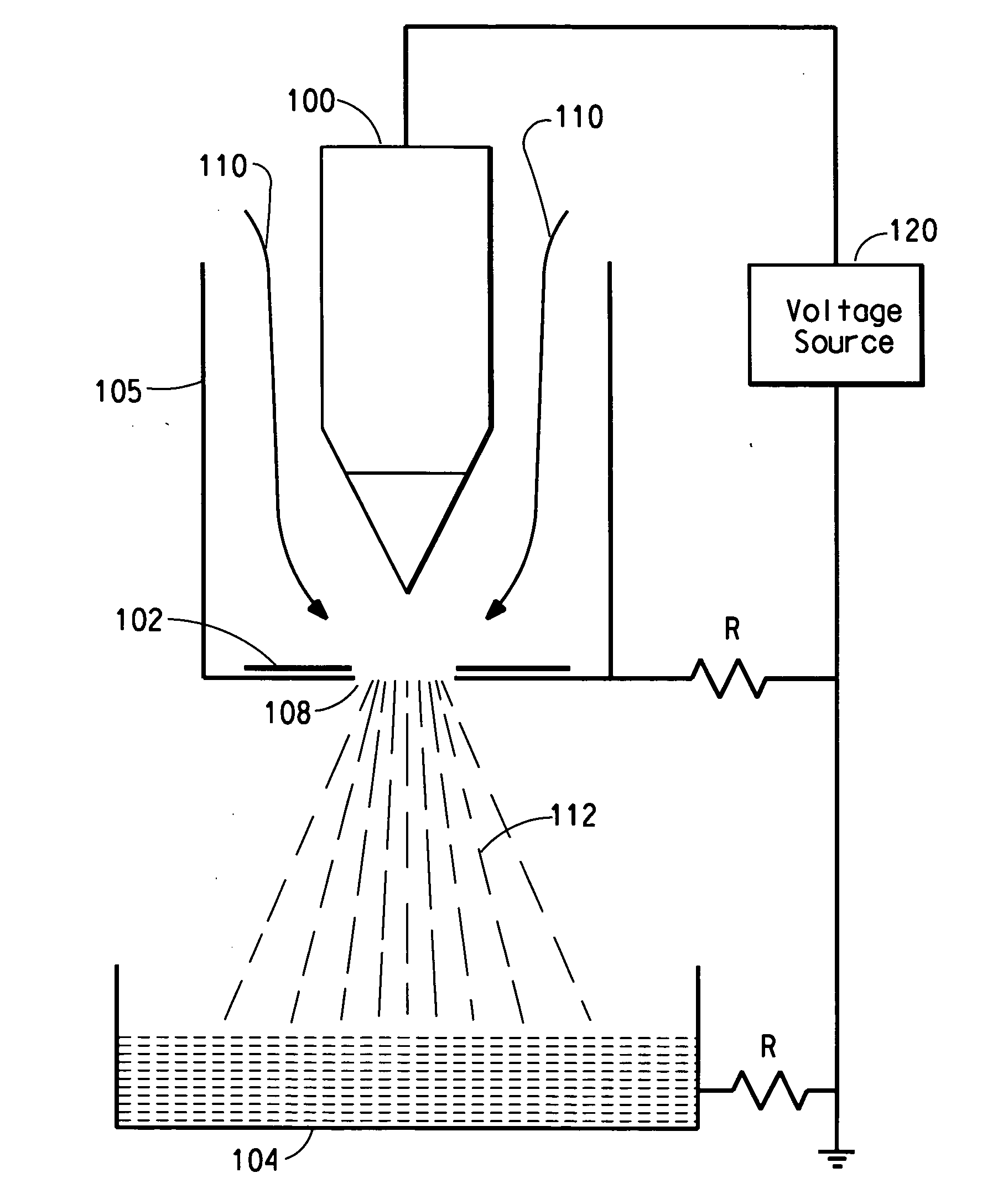
[0073] The polymer solution and parameters of Comparative Example 1 were repeated, except that the spinning temperature was 100° C., the pressure was 2.9 MPa and the flow rate was 2.4 cm3 / s and a voltage of 16 kV was applied to the emitter electrode. The resulting product was characterized by an interconnecting complex web of larger filaments which were further interconnected by complex webs of filaments having sub-micron widths as shown in FIGS. 8 and 9.

example 2

[0074] A solution of 7 wt. % Polymer B in Freon®-11 was prepared, supplied to the apparatus of FIG. 3 at a spin temperature of 105° C. and flash spun through a spin orifice having a diameter of 0.25 mm at a pressure of 2.5 MPa and a flow rate of 2.52 cm3 / s. A voltage of 16 kV was applied to the emitter electrode. The resulting product is shown in FIG. 10.

example 3

[0075] A solution of 18 wt. % Polymer C in Freon®-11 was prepared, supplied to the apparatus of FIG. 3 at a spin temperature of 101° C. and flash spun through a spin orifice having a diameter of 0.25 mm at a pressure of 2.5 MPa and a flow rate of 2.49 cm3 / s. A voltage of 14 kV was applied to the emitter electrode. The resulting product had no nanofibers and is shown in FIG. 11.


PUM

PropertyMeasurementUnit
Lengthaaaaaaaaaa
Lengthaaaaaaaaaa
Pore sizeaaaaaaaaaa

Abstract

A nonwoven fibrous structure and process for forming it, which is an interconnecting web of polyolefin filaments having filament widths greater than about 1 micrometer which are further interconnected with webs of smaller polyolefin filaments having filament widths less than about 1 micrometer, wherein the smaller polyolefin filaments comprise a majority of all filaments.

Description

BACKGROUND OF THE INVENTION [0001] Because of its large volume and favorable economics, the protective apparel market is a highly desirable one for nonwoven structures. This market comprises protection from hazardous chemicals in such diverse areas as spill clean-up, medical uses, and paint and asbestos removal. It has been long known that for a garment to be comfortable, it must easily allow the body to transfer heat and moisture to the environment. This goal is achieved when the garment is made with fabrics having low air flow resistance. At the same time, the garment needs to provide protection from the expected hazards. The degree of protection is dependent upon the effectiveness of the barrier characteristics of the fabric. The barrier characteristics have been correlated with fabric pore size, with the smallest pore size providing the most effective barrier properties. Unfortunately, smaller pore size also generally results in higher air flow resistance and a less comfortable ...

Claims


Application Information

Patent Timeline
IPC IPC(8): B32B3/00B32B3/26D04H1/4291D04H1/724D04H1/728
CPCD01D5/0023D01D5/0069D01D5/0092D01D5/11D01F6/04D04H3/166D01F6/30D01F6/46D04H3/02D04H3/16D01F6/06D04H1/724Y10T442/619Y10T442/614Y10T442/10Y10T428/249978Y10T442/626
Inventor WEINBERG, MARK GARYDEE, GREGORY T.HARDING, THOMAS WILLIAM
Owner EI DU PONT DE NEMOURS & CO
Learn More