
Production method of catalyst for fuel cell and of fuel cell, and catalyst for fuel cell and fuel cell

Inactive Publication Date: 2006-06-22
FUJITSU LTD
View PDF12 Cites 4 Cited by
  • Summary
  • Abstract
  • Description
  • Claims
  • Application Information

AI Technical Summary

Benefits of technology

[0016] It is another object of the present invention to provide a method for manufacturing a fuel cell having an excellent output characteristic using such the catalyst for the fuel cell as described above.

Problems solved by technology

However, in recent years, such devices are further made high-performance, the lithium secondary cells becoming unable to fully satisfy demands for highly functional operations as a driving power source.
Morevoer, when a catalyst to be used as an electrode of a fuel cell is formed, if metal fine particles are formed only by platinum, its active site is easily poisoned by carbon monoxide contained in fuel or air to be supplied or produced during catalyst reaction in some cases, which causes a life of the fuel cell to tend to be shortened.
However, when a catalyst is formed by using platinum and other metals to suppress poisoning caused by carbon monoxide, following problems occur.
However, this causes costs to be naturally increased when compared with the case in which the catalyst is formed by supporting only platinum on carbon particles.
Moreover, if this method is employed, due to occurrence of the two-step reducing reactions, metal fine partcles to be finally obtained become large in size, causing its specific area to tend to become smaller.
As a result, when the catalyst formed by the methods as described above is used as an electrode of a fuel cell, there is a fear that it is difficult to obtain an output being usable as a driving power source for high-performance devices in a stable manner.

Method used


Image

  • Production method of catalyst for fuel cell and of fuel cell, and catalyst for fuel cell and fuel cell
  • Production method of catalyst for fuel cell and of fuel cell, and catalyst for fuel cell and fuel cell
  • Production method of catalyst for fuel cell and of fuel cell, and catalyst for fuel cell and fuel cell

Examples


Embodiment Construction

[0029] Preferred embodiments of the present invention will be described below with reference to the accompanying drawings, wherein like reference numerals refer to like elements throughout.

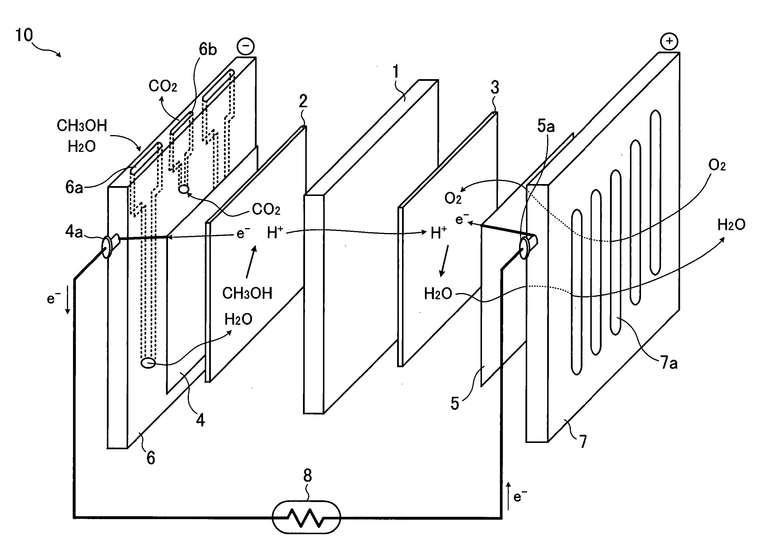
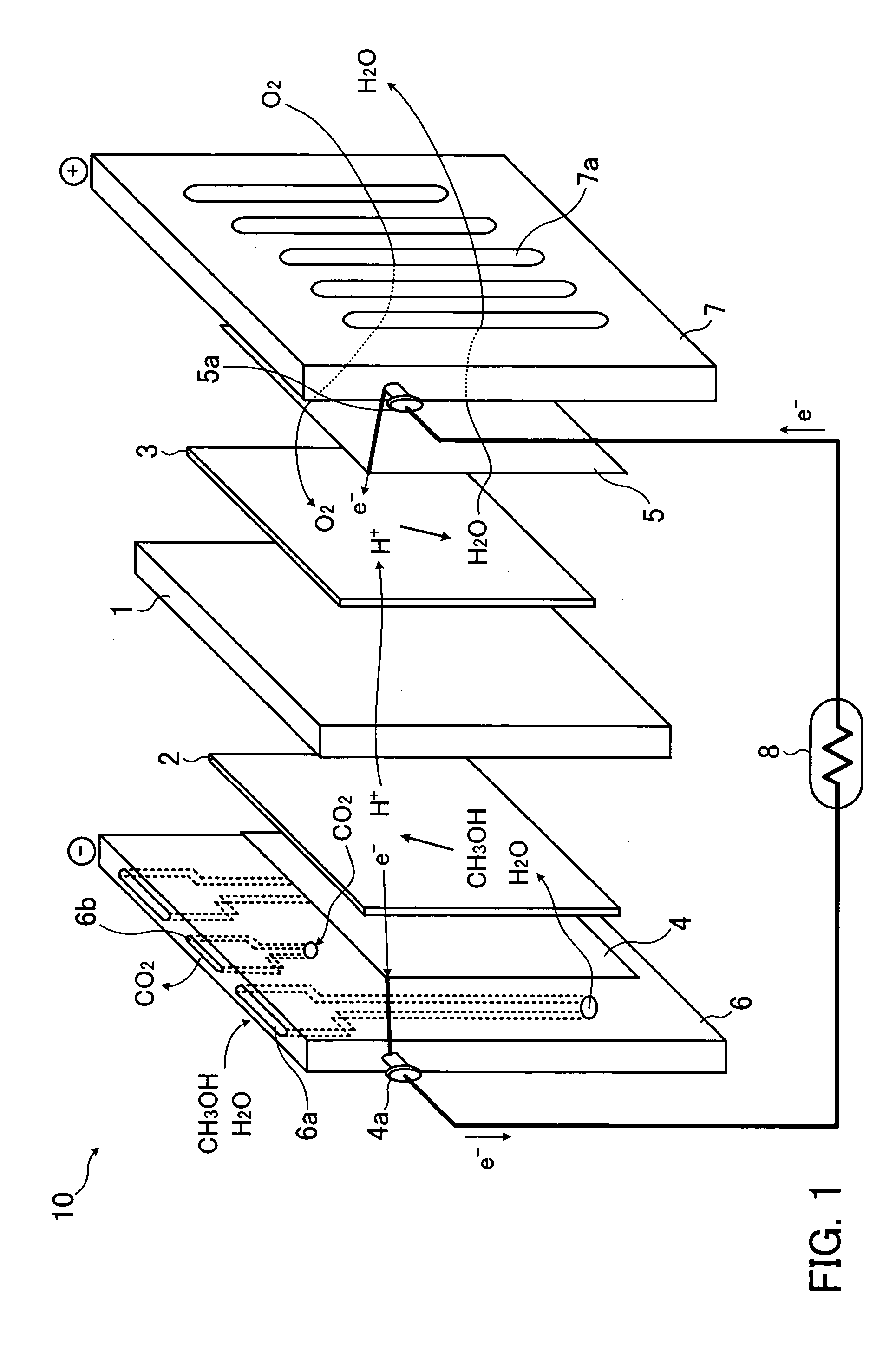
[0030]FIG. 1 shows operational principles and configurations of a fuel cell. The fuel cell 10 shown in FIG. 1 uses, as a solid electrolyte layer 1, for example, a fluororesin ion-exchange membrane such as a perfluoroalkyl sulfonic acid polyer membrane or the like having proton conductivity. As shown in FIG. 1, the solid electrolyte layer 1 is interposed between a fuel electrode 2 and an air electrode 3. Outside of the fuel electrode 2 are provided a current collector 4 and a flow path plate 6. Outside of the air electrode 3 are provided a current collector 5 and a flow path plate 7. Each of both the fuel electrode 2 and air electrode 3 is formed by using a catalyst obtained by supporting metal fine particles containing platinum and metal being different from another metal on a supporter such as a...


PUM

PropertyMeasurementUnit
Temperatureaaaaaaaaaa
Sizeaaaaaaaaaa

Abstract

A method for producing a catalyst for a fuel cell is provided which is capable of improving output characteristics of the fuel cell. Metal fine particles making up the catalyst for the fuel cell to be used as a fuel electrode and air electrode are formed by reducing platinum salt with molybdenum carbonyl. The catalyst for the fuel cell is formed by supporting platinum-molybdenum fine particles on carbon particles. By employing this reducing method, platinum-molybdenum fine particles being small in size and high in dispersibility can be obtained, making the catalyst for the fuel cell highly active. By constructing the fuel and air electrodes using the catalyst for the fuel cell, high outputs from the fuel cell are made possible.

Description

CROSS-REFERENCE TO RELATED APPLICATIONS [0001] This application is based upon and claims the benefits priority from the prior Japanese Patent Application No. 2004-366193, filed on Dec. 17, 2004, the entire contents which are incorporated herein by reference. BACKGROUND OF THE INVENTION [0002] 1. Field of the Invention [0003] The present invention relates to a method for producing a catalyst to be used for a fuel cell, a method for producing the fuel cell, and to a catalyst to be used in the fuel cell and the fuel cell, and particularly to the method for producing the catalyst to be used for the fuel cell using platinum or the like, the method for producing the fuel cell using, as an electrode, such a catalyst produced as above, and to the catalyst to be used in the fuel cell and the fuel cell to be produced by using such methods as described above. [0004] 2. Description of the Related Art [0005] Conventionally, a lithium secondary cell is widely used as a driving power source for mi...

Claims


Application Information

Patent Timeline
IPC IPC(8): B01J21/18H01M4/86B05D5/12
CPCB01J23/6525B01J23/8913B01J35/0013B01J37/06B01J37/086H01M4/8605H01M4/921H01M4/926H01M8/1004Y02E60/521Y02P70/50Y02E60/50B01J35/23
Inventor TSUTSUMI, MASAMIHIBINO, SEIJIYOSHIDA, HIROAKITAKEI, FUMIOTAKASU, YOUICHIYOSHIDA, KENSUKE
Owner FUJITSU LTD
Learn More