This helps you quickly interpret patents by identifying the three key elements:
Problems solved by technology
Method used
Benefits of technology
Benefits of technology
[0015] It is hence an object of the invention to provide a nonaqueous electrolyte secondary battery excellent in output characteristic such as large current discharge or pulse discharge in ordinary use, and effective in current suppression at an abnormal time such as external short-circuiting.
Problems solved by technology
However, when plural current collecting leads are connected to the electrodes as disclosed in Jpn. Pat. Appln. KOKAI Publication Nos. 11-317218 and 11-339758, the assembly procedure is complicated, and consequently, productivity of batteries is lowered.
In addition, when the battery is designed by reducing the thickness of the electrodes as in Jpn. Pat. Appln. KOKAI Publication No. 2002-110254, the occupying rate of current collectors in electrodes is larger, and the quantity of reaction substances such as active materials of electrodes is inevitably decreased.
This is significantly disadvantageous in terms of advance of larger capacity of the secondary battery.
On the other hand, the lithiumion secondary battery has other problems, that is, overcurrent flows in the battery in the event of an abnormality such as overcharge or short-circuiting, a nonaqueous electrolysis solution is decomposed, and a decomposition reaction of the electrolysis solution causes heat generation to raise the battery temperature, or liquid leaks or causes a rupture.
In the PTC element, however, since its material configuration and shape, especially shape aspects, function as relatively large resistance components, elevation of output of the secondary battery may be hindered.
Method used
Image
Click on the blue label to locate the original text in one second.
Reading with bidirectional positioning of images and text.
Examples
first embodiment
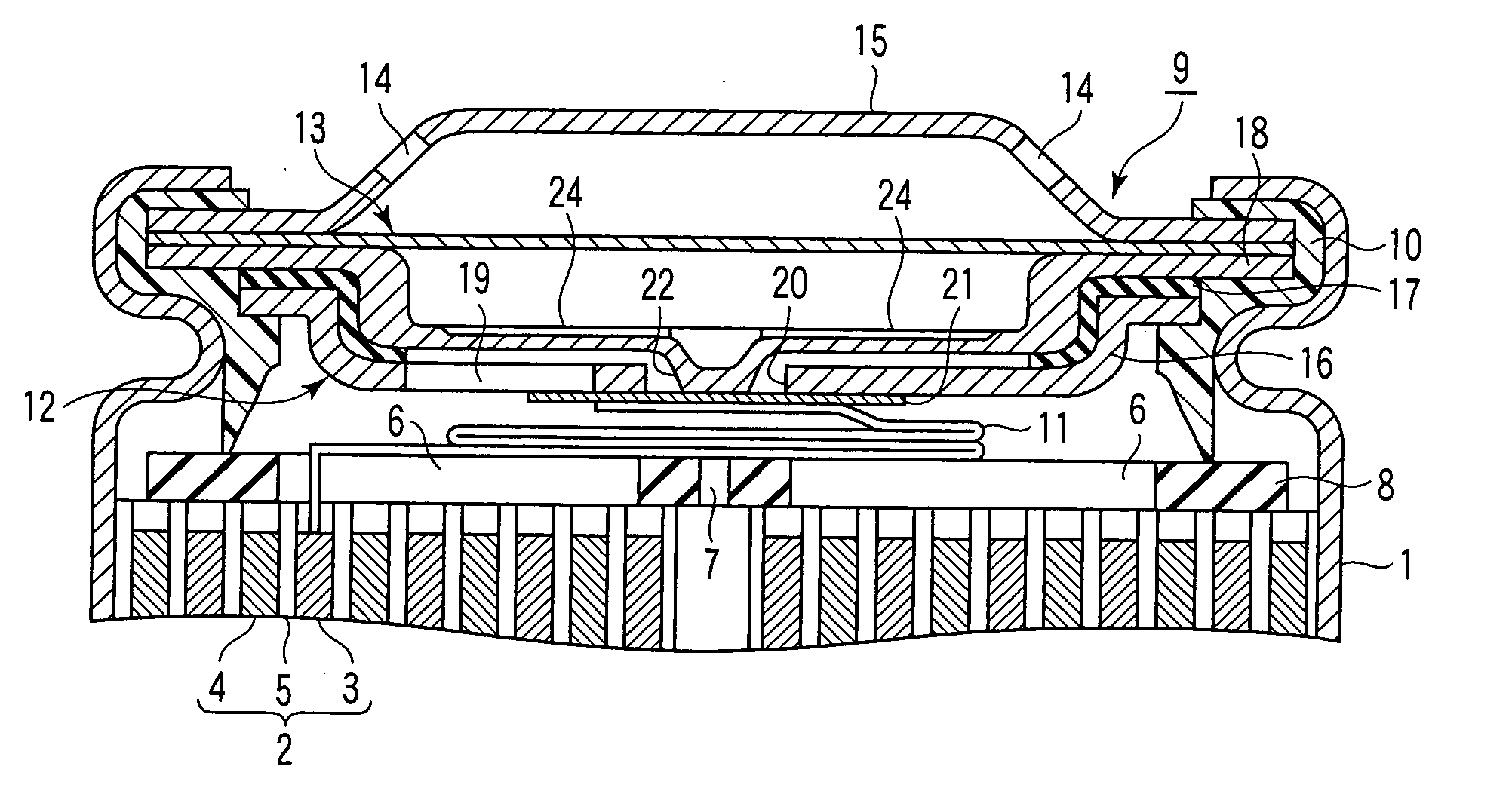
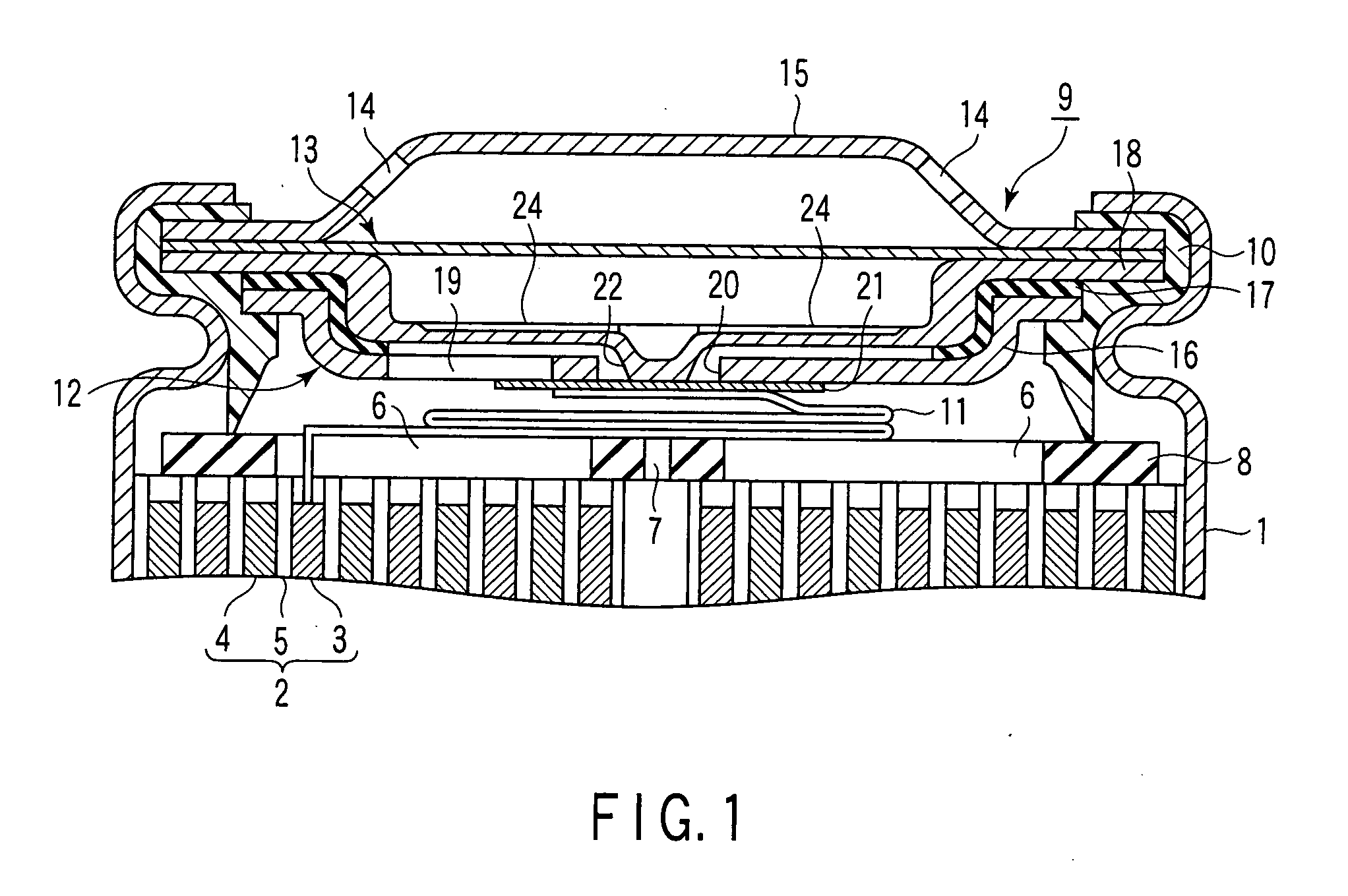
[0040]FIG. 1 is a partial sectional view showing a cylindrical nonaqueous electrolyte secondary battery according to a first embodiment of the invention; FIG. 2 is an exploded perspective view showing essential parts of a sealing lid group assembled in the cylindrical nonaqueous electrolyte secondary battery in FIG. 1; FIG. 3 is a plan view showing a PTC element assembled in the cylindrical nonaqueous electrolyte secondary battery in FIG. 1; and FIG. 4 is a sectional view taken along line IV-IV in FIG. 3.
[0041] As shown in FIG. 1, an external can 1 of cylindrical shape with a bottom is made of, for example, stainless steel or iron, and also functions as one polar terminal (for example, negative electrode terminal). In the bottom of the external can 1, an insulator (not shown) is disposed. An electrode assembly 2 is contained in the external can 1. The electrode assembly 2 is constituted of a positive electrode 3, a negative electrode 4, and a separator 5 interposed therebetween to ...
second embodiment
[0128]FIG. 11 is a partial sectional view showing a cylindrical nonaqueous electrolyte secondary battery according to a second embodiment of the invention, and FIG. 12 is an exploded perspective view showing essential parts of a sealing lid group assembled in the cylindrical nonaqueous electrolyte secondary battery in FIG. 11. In FIGS. 11 and 12, the same members as in FIGS. 1 and 2 are identified with same reference numerals, and explanation thereof is omitted.
[0129] In FIGS. 11 and 12, the sealing lid group 9 is composed of a conductive current breaking member 61, an insulating ring 62, a rupture plate 63, and a hat-shaped terminal plate 15 having a PTC element 13 and gas vents 14 and serving as the other polarity terminal (for example, positive electrode terminal), which are crimped and fixed in this order by the insulating gasket 10 at their peripheral edges.
[0130] The current breaking member 61 is formed like a dish as shown in FIG. 12, and a peripheral edge of the current br...
third embodiment
[0139]FIG. 13 is a partial sectional view showing a cylindrical nonaqueous electrolyte secondary battery according to a third embodiment of the invention, and FIG. 14 is an exploded perspective view showing essential parts of a sealing lid group assembled in the cylindrical nonaqueous electrolyte secondary battery in FIG. 13. In FIGS. 13 and 14, the same members as in FIGS. 1 and 2 are identified with same reference numerals, and explanation thereof is omitted.
[0140] In FIGS. 13 and 14, the sealing lid group 9 is composed of a rupture plate 71, a PTC element 13, a first half insulating ring 72, a current breaking member 73, a second half insulating ring 74, and a hat-shaped terminal plate 15 having gas vents 14 opened and serving as the other polarity terminal (for example, positive electrode terminal), which are crimped and fixed in this order from the electrode assembly 2 side by the insulating gasket 10 at their peripheral edges.
[0141] The rupture plate 71 is formed like a dish...
PUM
Abstract
The invention provides a nonaqueous electrolyte secondary battery excellent in output characteristic such as large current discharge or pulse discharge in ordinary use, high in safety by preventing destruction due to suppression of current in an abnormality such as external short-circuiting, and further large in capacity. The nonaqueous electrolyte secondary battery comprises an external can opened at one end thereof, an electrodeassembly contained in the external can, and comprising a negative electrode, a separator and a positive electrode, a nonaqueous electrolyte contained in the external can, and a sealing lid group tightly sealed at the opening of the external can by way of an insulating member, wherein the sealing lid group includes an intact plate-like PTC element having a fragile portion to be easily broken due to elevation of internal pressure by gas generation.
Description
CROSS-REFERENCE TO RELATED APPLICATIONS [0001] This is a Continuation Application of PCT Application No. PCT / JP2004 / 004846, filed Apr. 2, 2004, which was published under PCT Article 21(2) in Japanese. [0002] This application is based upon and claims the benefit of priority from prior Japanese Patent Application No. 2003-102021, filed Apr. 4, 2003, the entire contents of which are incorporated herein by reference. BACKGROUND OF THE INVENTION [0003] 1. Field of the Invention [0004] The present invention relates to a nonaqueous electrolyte secondary battery. [0005] 2. Description of the Related Art [0006] Recently, along with a downsizing trend of electronic appliances such as cellular phones and portable personal computers and an increase in demand for them, there is a mounting demand for higher performance in secondary batteries used as a power source of these electronic appliances. To meet such a demand, nonaqueous electrolyte batteries using a material, such as a carbon material, c...
Claims
Application Information
Patent Timeline
Application Date:The date an application was filed.
Publication Date:The date a patent or application was officially published.
First Publication Date:The earliest publication date of a patent with the same application number.
Issue Date:Publication date of the patent grant document.
PCT Entry Date:The Entry date of PCT National Phase.
Estimated Expiry Date:The statutory expiry date of a patent right according to the Patent Law, and it is the longest term of protection that the patent right can achieve without the termination of the patent right due to other reasons(Term extension factor has been taken into account ).
Invalid Date:Actual expiry date is based on effective date or publication date of legal transaction data of invalid patent.

