Capacitive sensor

a capacitive sensor and sensor technology, applied in the direction of acceleration measurement using interia force, instrumentation, person identification, etc., can solve the problems of reducing the detecting accuracy, unable to remove the noise flowing in from the human body, etc., and achieve the effect of simplifying the structure of the detecting circuit for carrying out the subsequent signal processing and easy removal of the noise delivered from the human body

Inactive Publication Date: 2006-06-29
ALPS ALPINE CO LTD
View PDF5 Cites 60 Cited by
  • Summary
  • Abstract
  • Description
  • Claims
  • Application Information

AI Technical Summary

Benefits of technology

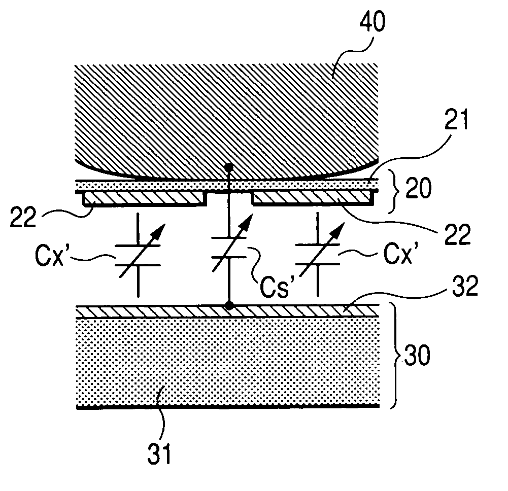
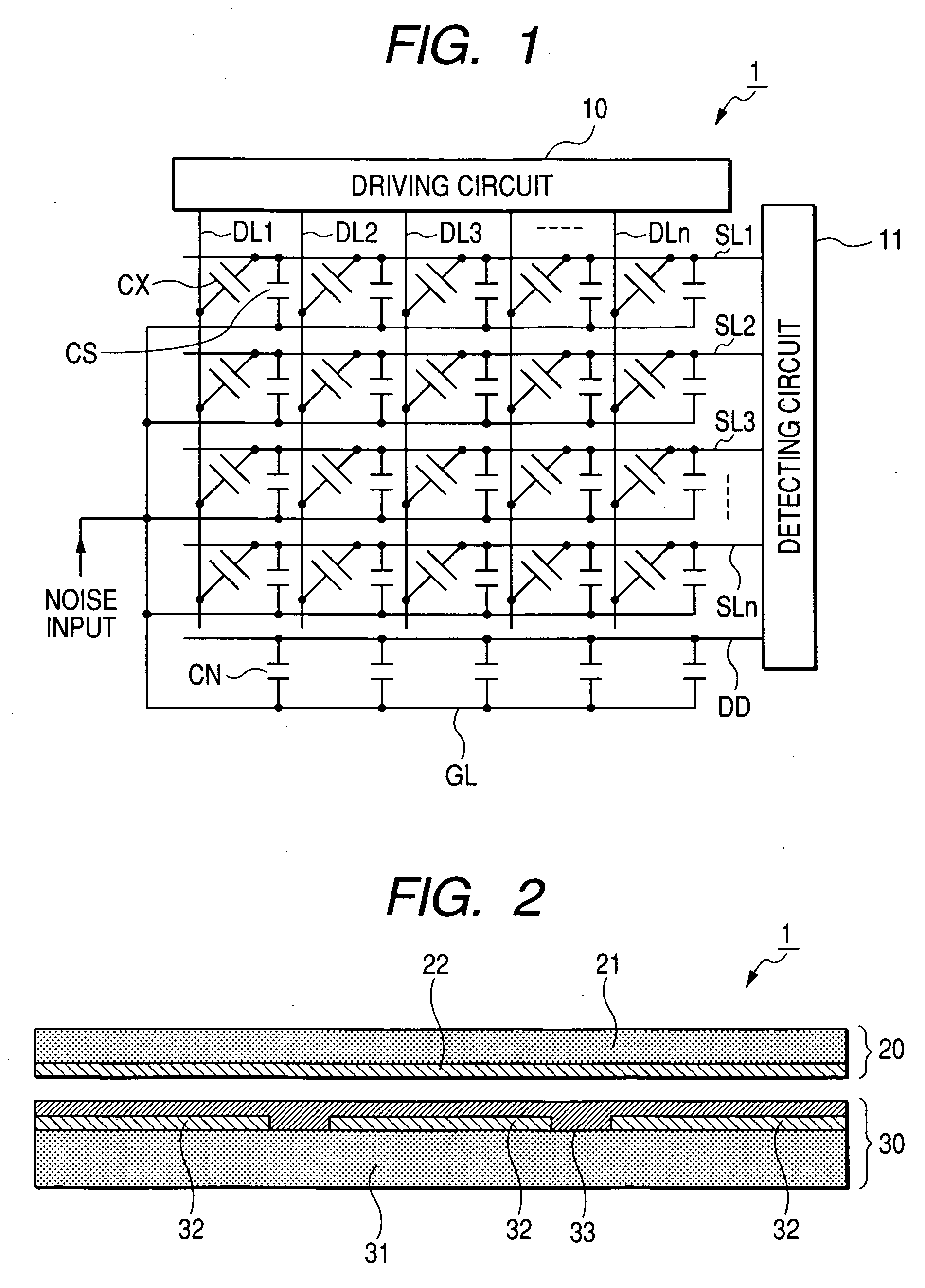
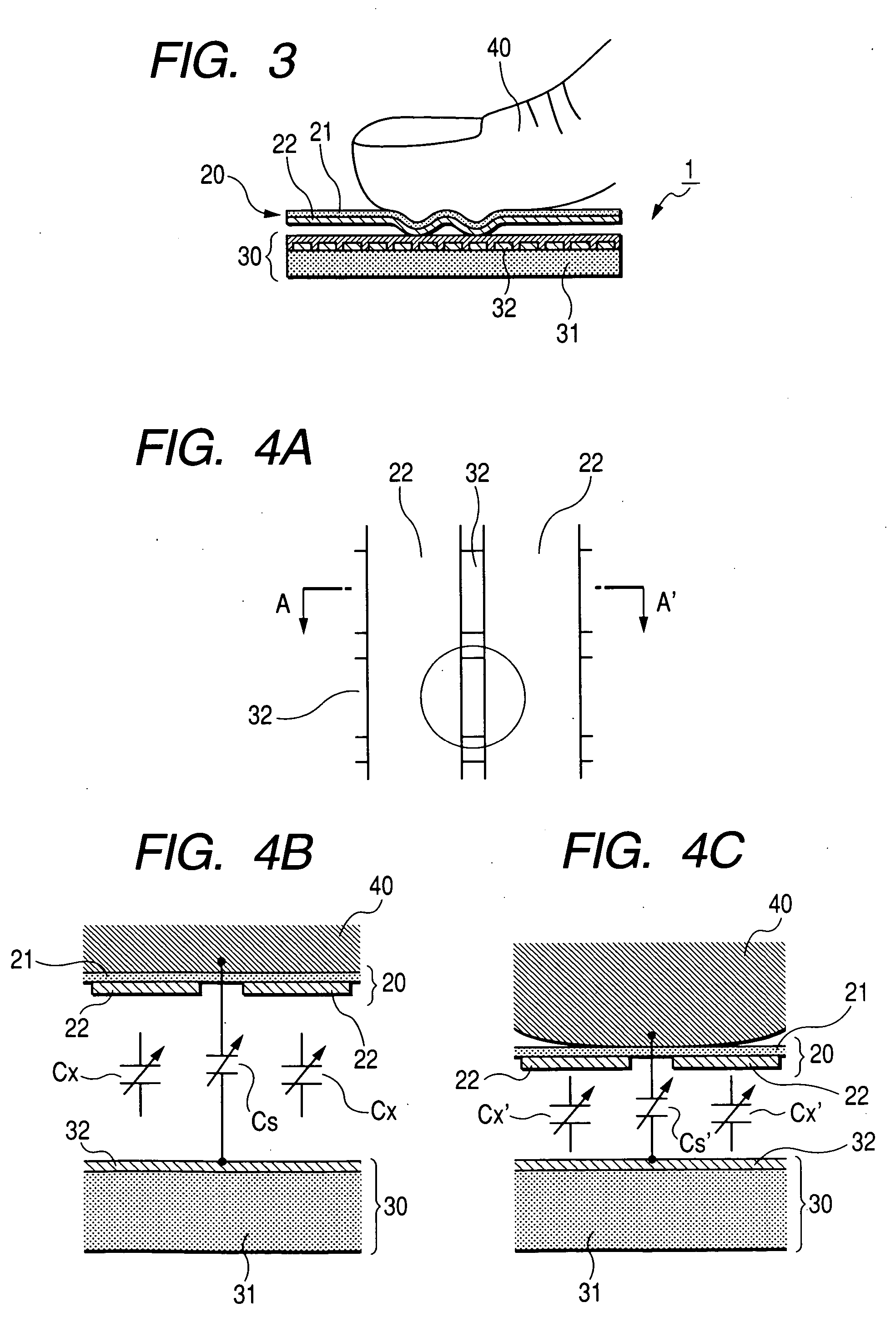
[0009] One aspect of the invention is a pressure-sensitive capacitive sensor, including a sensor unit having a first substrate 20 where a plurality of vertical wiring lines 22 is formed; and a second substrate 30 where a plurality of horizontal wiring lines 32 is formed, the first and second substrates being disposed in a matrix and facing each other with a gap therebetween, and the capacitance at the intersections between the vertical wiring lines and the horizontal wiring lines changed according to external pressure; and a detecting unit for detecting the change in the capacitance at the intersections between the vertical wiring lines and the horizontal wiring lines and detecting an externally applied pressure distribution based on the detecting result. In this case, a horizontal wiring line 50 for noise detection is disposed on a surface where the horizontal wiring lines are formed on the second substrate.
[0010] In the above pressure-sensitive capacitive sensor, the first substrate where a plurality of horizontal wiring lines is formed and the second substrate where a plurality of vertical wiring lines is formed face each other with a gap therebetween, and the first and second substrates have a matrix formed by the horizontal and vertical wiring lines, and the horizontal wiring line for noise detection is disposed on a surface of the second substrate where the horizontal wiring lines are formed.
[0011] In addition, the capacitive sensor includes a sensor unit and a detecting unit, and the sensor unit senses the change in the capacitance at the intersections between the horizontal wiring lines and the vertical wiring lines in response to an externally applied pressure, and the detecting unit detects the change in the capacitance at the intersections between the horizontal wiring lines and the vertical wiring, thereby an externally applied pressure distribution is detected based on the corresponding detecting result.
[0012] Therefore, according to the

Problems solved by technology

That is, the noises are flowed in due to parasitic capacitances which occur between the fingerprint and detecting wiring lines at positions where driving wiring lines (vertical electrode) and the detecting wiring lines (horizontal wiring lines) are dispos

Method used


Image

  • Capacitive sensor
  • Capacitive sensor
  • Capacitive sensor

Examples


first embodiment

[0056]FIG. 5 shows a structure of the pressure-sensitive capacitive sensor according to a first embodiment of the invention. Meanwhile, since the gist of the invention lies in the structure of the capacitive sensor, the gist of the invention is not limited to the present embodiment, and the electric structure is omitted in each embodiment. FIG. 5A is a plan view seen from the first substrate 20 (film shaped substrate) of the capacitive sensor, and FIG. 5B is a cross-sectional view taken along B-B′ line of FIG. 5A. The Same reference numerals are attached to the same members as those of the capacitive sensor shown in FIGS. 2 to 4.

[0057] The pressure-sensitive capacitive sensor 1 according to the first embodiment of the invention includes the first substrate 20 where a plurality of vertical wiring lines 22 is formed; and the second substrate 30 where a plurality of horizontal wiring lines 32 is formed. The first and second substrates face each other with a spacer 45 interposed thereb...

second embodiment

[0066] Next, FIG. 6 shows a structure of the pressure-sensitive capacitive sensor according to the second embodiment of the invention. FIG. 6A is a plan view of the sensor unit of the capacitive sensor, and FIG. 6B is a cross-sectional view taken along line C-C′ of FIG. 6A.

[0067] The capacitive sensor according to the second embodiment differs from the capacitive sensor according to the first embodiment in that vertical wiring lines and the horizontal wiring lines are divided into two areas in the first and second substrates, respectively, and are disposed in a matrix, and the horizontal wiring line 50 for noise detection is disposed at a position corresponding to an interface (i.e. central position) between the two areas in the second substrate 30 such that it does not cross the vertical wiring lines, and the rest structures are the same thereby overlapping descriptions will be omitted.

[0068] In FIG. 6, same reference numerals are applied to the same components as the capacitive ...

third embodiment

[0072] Next, FIG. 7 shows a structure of the pressure-sensitive capacitive sensor according to a third embodiment of the invention.

[0073]FIG. 7A is a plan view of the sensor unit of the capacitive sensor, and FIG. 7B is a cross-sectional view taken along line D-D′ of FIG. 7A.

[0074] The capacitive sensor according to the third embodiment differs from the capacitive sensor according to the second embodiment in that vertical wiring lines and horizontal wiring lines are divided into two areas having the inclined area used as an interface area between the two areas, thereby the wiring lines are disposed in a matrix, and the horizontal wiring line 60 for noise detection is formed at a position corresponding to the interface area between the two areas in the second substrate 30 not to cross the vertical wiring lines. Since the rest structures are the same as those of the fourth embodiment, the descriptions thereabout will be omitted.

[0075] In FIG. 7, the first substrate 20 is divided in...


PUM


Abstract

A pressure-sensitive capacitive sensor is provided that can easily remove noises delivered from a human body. The capacitive sensor includes a sensor unit having a first substrate where a plurality of vertical wiring lines is formed and a second substrate where a plurality of horizontal wiring lines is formed, the first and second substrates being disposed in a matrix and facing each other with a gap interposed therebetween, and a capacitance at intersections between the vertical wiring lines and the horizontal wiring lines changed in response to an external pressure; and a detecting unit for detecting the change in capacitance at the intersections between the vertical wiring lines and the horizontal wiring lines, and detecting an externally applied pressure distribution based on the detecting result. In this case, a horizontal wiring line 50 for noise detection is disposed on a surface where the horizontal wiring lines are formed in the second substrate.

Description

BACKGROUND OF THE INVENTION [0001] 1. Field of the Invention [0002] The present invention relates to a capacitive sensor, and, more particularly, to a pressure-sensitive capacitive sensor preferably used as a fingerprint sensor. [0003] 2. Description of the Related Art [0004] A surface pressure distribution sensor for sensing a fine unevenness is used as a fingerprint sensor or the like. FIG. 17 shows a related art. As shown in FIG. 17, the fingerprint scanning device (i.e. fingerprint sensor) includes a first electrode group 12 consisting of a plurality of verticals extending in a first direction; a second electrode group 14 consisting of a plurality of horizontals extending in a second direction crossing the first direction and disposed on the first electrode group with an interlayer insulating film 13 interposed between the first and second electrode groups; a fingerprint scanning sensor having a surface protective layer 15 made of a dielectric substance disposed on the second el...

Claims


Application Information

Patent Timeline
IPC IPC(8): H01L29/84
CPCG01L1/146G06F3/0414G06F3/044G06K9/0002G06F3/0447G06F3/0445G06F3/0446G06V40/1306G01L1/14A61B5/117
Inventor SAITO, JUNICHIITO, TAKUO
Owner ALPS ALPINE CO LTD
Why Eureka
Try Eureka