Method and device for manufacturing support body for run flat

Inactive Publication Date: 2006-06-29
YOKOHAMA RUBBER CO LTD
View PDF20 Cites 2 Cited by
  • Summary
  • Abstract
  • Description
  • Claims
  • Application Information

AI Technical Summary

Benefits of technology

[0006] An object of the present invention is to provide a method and device for manufacturing a support body for run flat that can achieve stable, efficient provision of annular shells with highly accurate dimensions.
[0009] According to the present invention, as described above, the inner molding roller has the maximum outer diameter that is substantially the same as the inner diameter of a tubular blank, a workpiece. For this reason, the tubular blank is stably supported by the entire side surface of the inner molding roller and thus the tubular blank never vibrates during the molding processing. Thus, the prevention of vibration allows processing of the tubular blank into an annular shell with highly accurate dimensions. In addition, an annular shell with highly accurate dimensions can provide excellent ride comfort during run-flat driving. Furthermore, since stabilization in the molding processibility can increase the rotational speed of the molding rollers, it is possible to improve productivity.

Problems solved by technology

Since the annular shell 33 constituting the support body for run flat serves to support a vehicle during run-flat driving, there is a problem that the dimensional accuracy of the annular shell 33 influences ride quality.
For the reasons described below, this molding device, however, has a problem that it is difficult to produce annular shells with a high degree of precision.
In this way the tubular blank vibrates, causing a reduction in processing accuracy.
The generation of this vibration is more much likely to occur as the rotational speed of the molding rollers is increased, i.e., as the molding speed is increased, thus resulting in the reduction of productivity.

Method used


Image

  • Method and device for manufacturing support body for run flat
  • Method and device for manufacturing support body for run flat
  • Method and device for manufacturing support body for run flat

Examples


Embodiment Construction

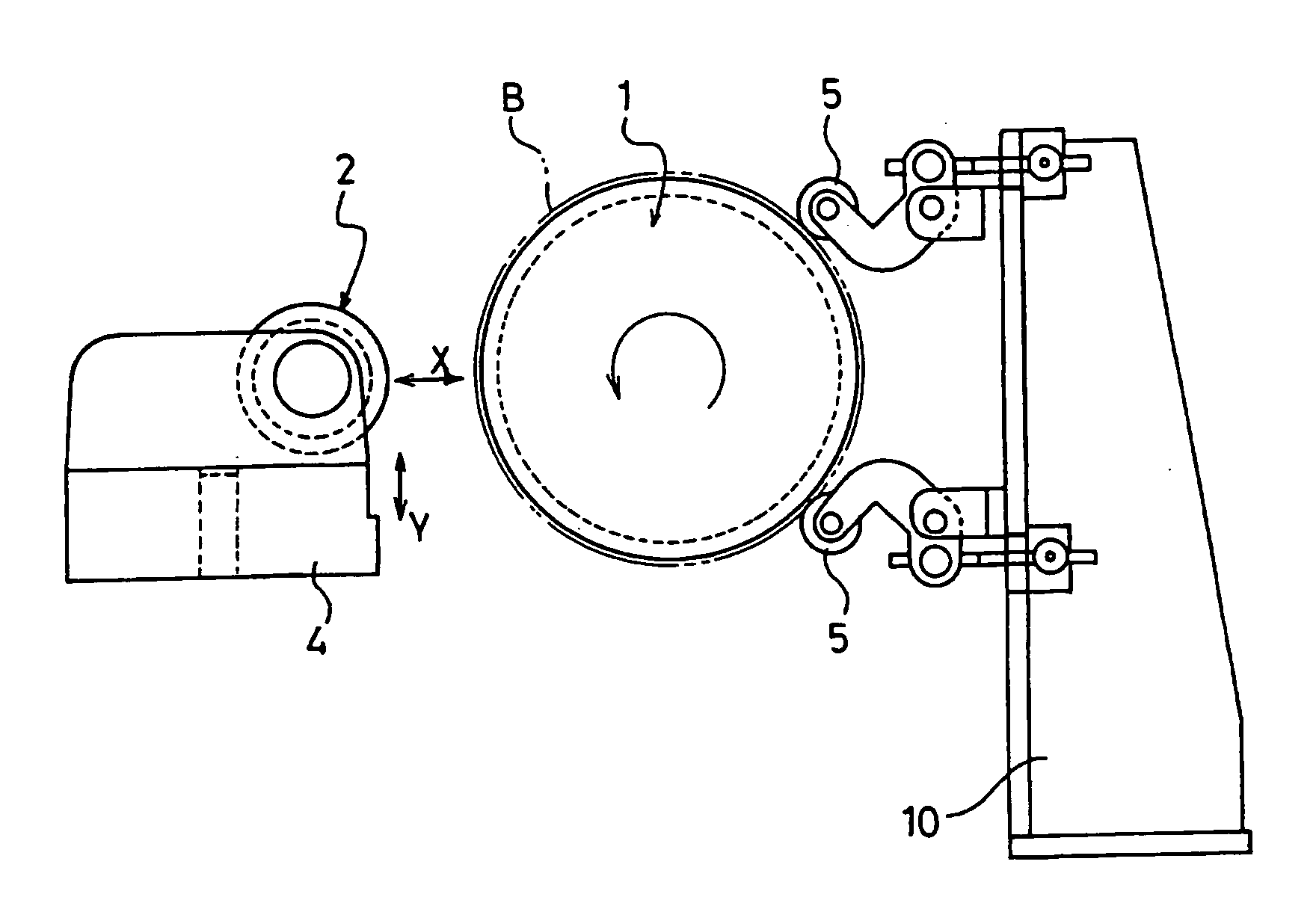
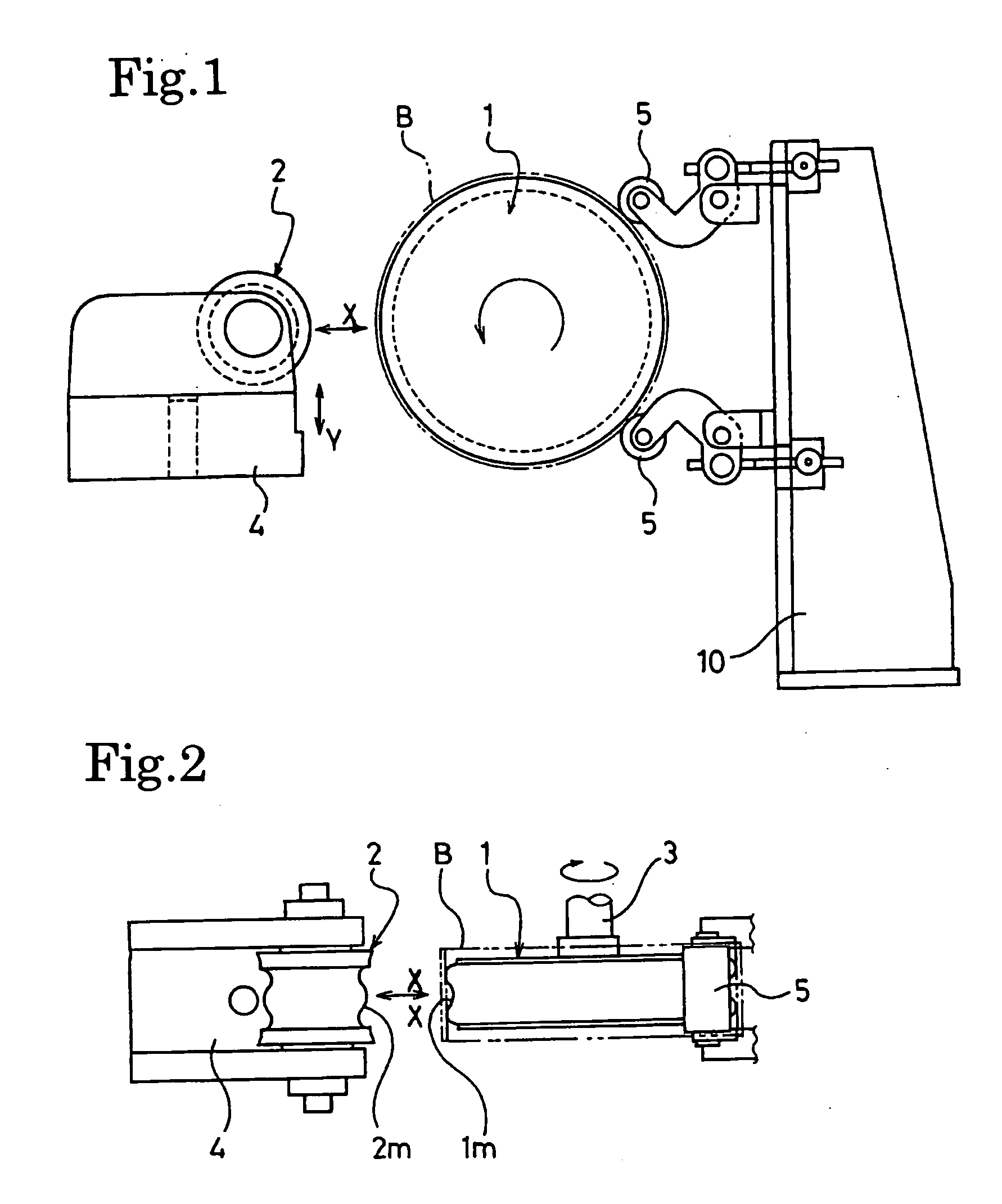
[0016] The term “tubular blank” as used in the present invention means an intermediate blank material before molded into an annular shell, a support body for run flat. In general, metallic materials are used for such an intermediate blank material. Although the production method for a tubular blank is not specifically limited, a tubular blank that is obtained by rolling up a rectangular-shaped flat metallic plate into a cylinder and welding the ends of the metallic plate together is preferable. Desirably, the welded portions are further polished for smoothness. Alternatively, a tubular body may be used that can be obtained by slicing a steel tube with a predetermined inner diameter into predetermined length pieces.

[0017] The metallic material constituting a tubular blank is not specifically limited as long as it has strength enough to support a vehicle during run-flat driving. In order to ensure excellent durability, however, a metallic material that produces a shear stress of 600 ...


PUM

PropertyMeasurementUnit
Fractionaaaaaaaaaa
Fractionaaaaaaaaaa
Diameteraaaaaaaaaa

Abstract

A method of manufacturing a support body for run flat, wherein in a case where the circumferential wall of a tubular blank B is pressingly held between inner and outer molding rollers 1 and 2 and where the molding rollers 1 and 2 are rotated to form at least one circumferentially continuous protruding part on the circumferential wall of the tubular blank B to process the tubular blank B into an annular shell, a molding roller having the maximum outer diameter that is substantially the same as the inner diameter of the tubular blank B is used as the inner molding roller 1.

Description

TECHNICAL FIELD [0001] The present invention relates to a method and device for manufacturing a support body for run flat. More specifically, the present invention relates to a method and device for manufacturing a support body for run flat that can achieve stable provision of annular shells with highly accurate dimensions. BACKGROUND ART [0002] There are many run-flat technologies that have been proposed for enabling a vehicle to continue traveling for several hundred kilometers even after pneumatic tires have been punctured during traveling. Among these proposals, as shown in FIG. 5, Patent Document 1 and the like propose a structure in which an annular support body 32 is attached on a rim 30 provided inside the hollow space of a pneumatic tire 31 incorporated in the rim and thereby the annular support body 32 supports the flat tire 31 to make run-flat driving possible. The support body 32 for run flat is constituted in such a way that elastic rings 34, 34 such as rubber are attac...

Claims


Application Information

Patent Timeline
IPC IPC(8): B29C59/04B29C35/02B21D17/04B21H1/10B60B21/02B60C17/04
CPCB21D17/04B21H1/10B60B21/12B60C17/04
Inventor SANO, TAKUZOTAKADA, NOBORU
Owner YOKOHAMA RUBBER CO LTD
Why Eureka
Try Eureka