
Surface light source device and display apparatus using the same

a technology of surface light source and display apparatus, which is applied in the direction of lighting device details, lighting and heating apparatus, instruments, etc., can solve the problems of color irregularity, less luminance, and less light leakage, so as to suppress color irregularities.

Inactive Publication Date: 2006-06-29
MITSUBISHI ELECTRIC CORP
View PDF16 Cites 21 Cited by
  • Summary
  • Abstract
  • Description
  • Claims
  • Application Information

AI Technical Summary

Benefits of technology

[0008] The invention provides a surface light source device that has a reflection sheet and that is enabled to prevent occurrence of color irregularity and luminance unevenness. The invention also provides a liquid crystal display apparatus that employs this surface light source device and that is enabled to obtain excellent display characteristics.
[0010] According to the invention, the reflection sheet has the reflection region, which is provided at the side opposite to the light source and is adapted so that the reflectance at shorter wavelengths of the wavelength region of visible light outputted from the light source is higher than the reflectance at longer wavelengths of the wavelength region of the visible light. Thus, the color irregularity, which is more likely to occur at a part in the display surface and as the distance of this part from the light source increases, and which causes the color of such apart to change to red, is cancelled. Thus, at a part provided at the side opposite to the light source in the display surface of the display apparatus, the color irregularity can be suppressed.

Problems solved by technology

Thus, excessive light, which may cause leakage of light, is absorbed by the color printed-dot portion.
Thus, the related surface light source device disclosed in JP-A-8-240720 has a problem in that as the distance of a part in the display surface of a liquid crystal apparatus from a light source increases, color irregularity is more likely to occur in such a part in the display surface so that the color of such a part in the display surface changes to red.
Thus, luminance is uneven in this related device, so that the luminance in the vicinity of the light emitting diode is high, and that as the distance of a place from the light emitting diode increases, the luminance decreases.
This unevenness of the luminance of illuminating light in the surface light source device results in problems that luminance unevenness and color irregularity occur in a displayed image, and that the quality of the image is degraded.

Method used


Image

  • Surface light source device and display apparatus using the same
  • Surface light source device and display apparatus using the same
  • Surface light source device and display apparatus using the same

Examples


first embodiment

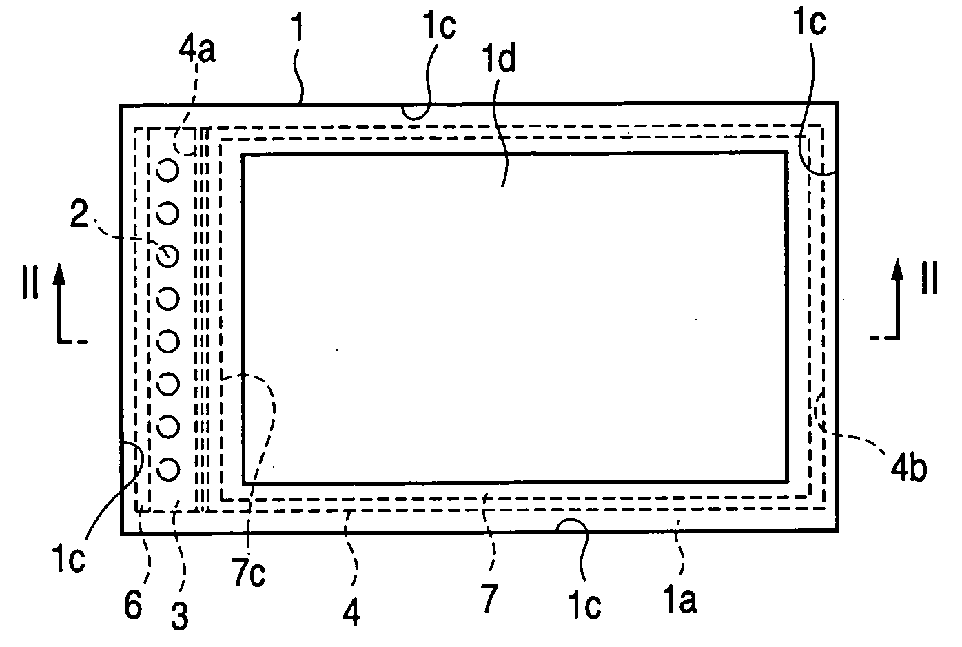
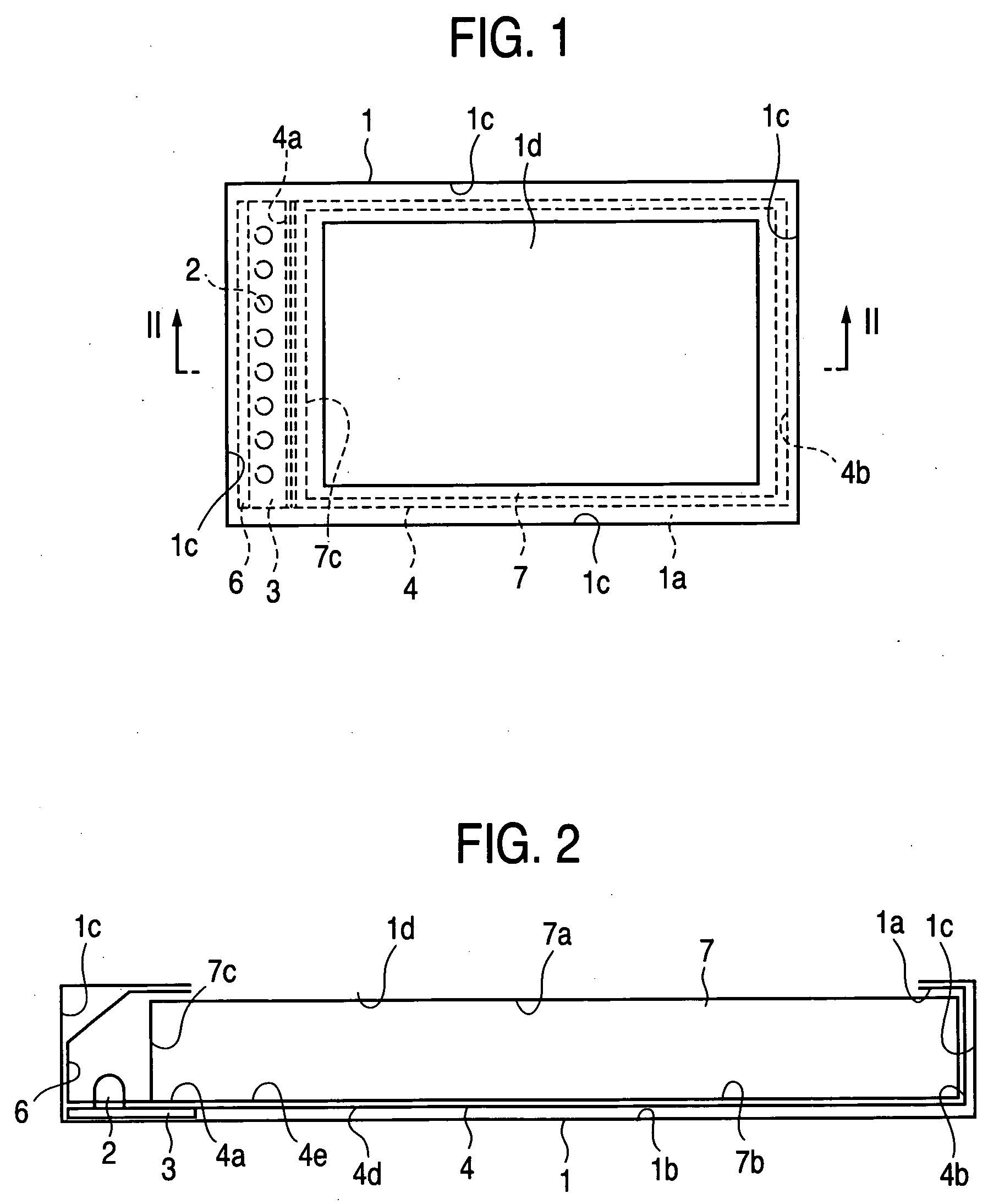
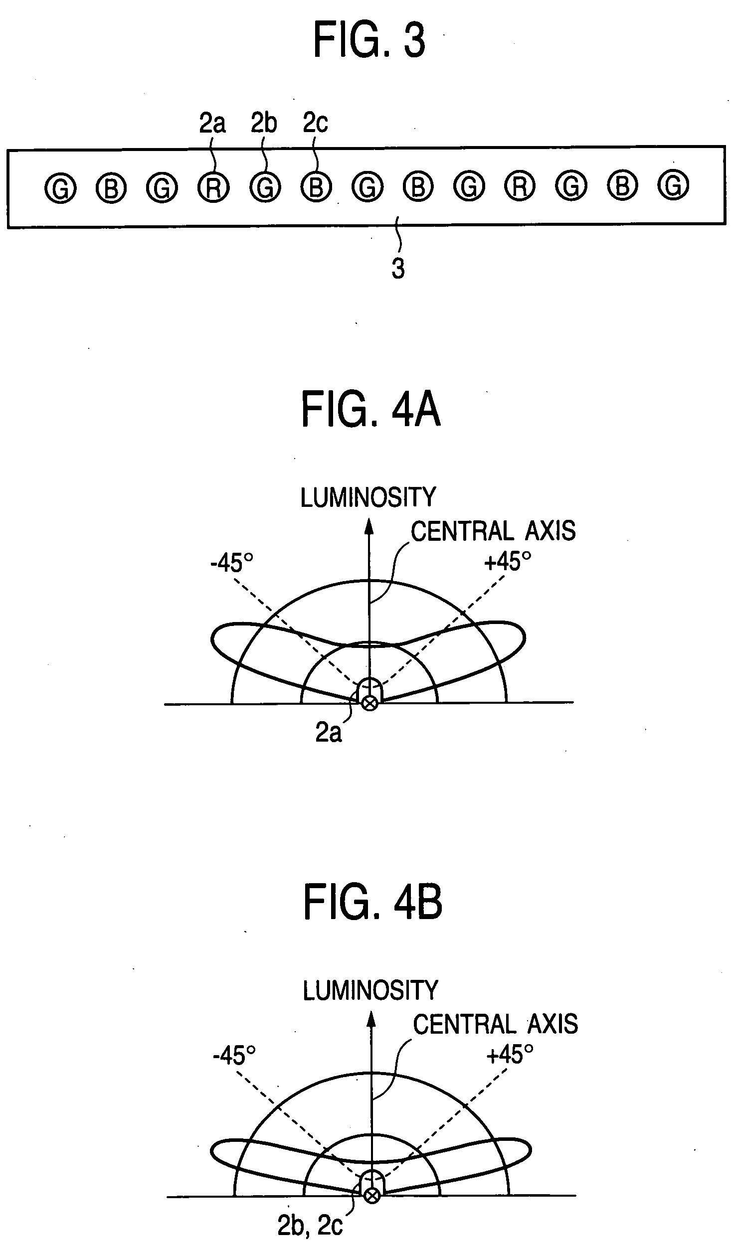
[0031]FIG. 1 is a plan view illustrating an outline of the configuration of a surface light source device according to a first embodiment of the invention. FIG. 2 is a partial cross-sectional view of the surface light source device, which is taken on line II-II shown in FIG. 1. FIG. 3 is a view illustrating an example of point-like light sources using light emitting diodes (LEDs).FIGS. 4A and 4B are luminosity distribution graphs illustrating the light distribution of the light emitting diode. FIG. 4A is a luminosity distribution graph illustrating the light distribution of a red light emitting diode. FIG. 4B is a luminosity distribution graph illustrating the light distribution of a blue / green light emitting diode. FIGS. 5A to 5C are plan views illustrating color patterns of a reflection sheet. FIG. 5A is a plan view of a reflection sheet in a case where a light source is disposed only in the vicinity of one side surface of a housing. FIG. 5B is a plan view of the reflection sheet ...

second embodiment

[0092]FIG. 6 is a plan view illustrating an outline of the configuration of a surface light source device according to a second embodiment of the invention. FIG. 7 is a partial cross-sectional view of the surface light source device, which is taken on line VII-VII shown in FIG. 6. Incidentally, in FIGS. 6 and 7, the same or corresponding components are designated by same reference characters as used to denote such components of the first embodiment. Thus, the description of such components is omitted herein.

[0093] Reference numeral 9 designates a color mixing light guide plate. Each of the color mixing light guide plates 9 has a pair of a top surface 9a and a bottom surface 9b, which are opposed to each other, and an incidence surface 9c and an output surface 9b, which are a pair of opposed side surfaces, among plural side surfaces defined by connecting edges of the top surface 9a and the bottom surface 9b. Preferably, all surface of the color mixing light guide plate 9 are mirror ...

third embodiment

[0106]FIG. 8 is a plan view illustrating an outline of the configuration of a surface light source device according to a third embodiment of the invention. FIG. 9 is a partial cross-sectional view of the surface light source device, which is taken on line IX-IX shown in FIG. 8. FIGS. 10A and 10B are plan views illustrating color patterns of a reflection sheet. FIG. 10A is a plan view of a reflection sheet, which illustrates an example of the color pattern in a case where a light source is disposed only in the vicinity of one side surface of a housing and FIG. 10B is a plan view of the reflection sheet, which illustrates one example of the color pattern in a case where the light source is disposed in the vicinity of each of two opposed side surfaces of the housing. FIGS. 11A to 11C are plan views illustrating color patterns of a reflection sheet; FIG. 11A is a plan view of a reflection sheet, which shows another example of the color pattern in a case where a light source is disposed ...


PUM


Abstract

A surface light source device includes a housing having an opening portion provided in a top surface thereof, a reflection sheet disposed on a bottom surface of the housing, a light guide plate disposed on the reflection sheet on a side of the opening, and a light source disposed on at least one of side surfaces of the housing. The reflection sheet has a first reflection region on a side opposite to the light source, and a reflectance of the first reflection region at shorter wavelengths in a wavelength region of visible light outputted from the light source is higher than a reflectance at longer wavelengths in the wavelength region of the visible light.

Description

BACKGROUND OF THE INVENTION [0001] 1. Field of the Invention [0002] The present invention relates to a surface light source device, in which a reflection sheet is colored, and to a display apparatus using this device. [0003] 2. Description of the Related Art [0004] A related surface light source device (see, for example, JP-A-8-240720 (page 4, left column, line 39 to right column, line 27, and FIG. 1)) has a color printed-dot portion that is provided on the top surface of a reflection sheet placed in the vicinity of a light entrance end surface of a light guide plate. Thus, excessive light, which may cause leakage of light, is absorbed by the color printed-dot portion. Consequently, leakage of light, which impair display quality, can be prevented from occurring at an end portion of a screen in the vicinity of a fluorescent tube 36. [0005] Another related surface light source device is constituted by a light distributing means, a light emitting diode, a reflecting means provided to f...

Claims


Application Information

Patent Timeline
Patent Type & Authority Applications(United States)
IPC IPC(8): F21V7/04
CPCG02B6/0043G02B6/0061G02B6/0076G02B6/0078G02F1/133609G02F1/1335
Inventor SAKAI, SEIJIYONEDA, TOSHIYUKI
Owner MITSUBISHI ELECTRIC CORP
Learn More