
Method and apparatus for reduction of compression noise in compressed video images

a compression noise and video image technology, applied in the field of compression noise reduction in compressed video image information, can solve the problems of deteriorating the quality of displayed video images and scenes, and heavily compressed videos exhibit a higher level of compression noise, so as to reduce the compression noise of the incoming video signal more effectively and efficiently

Inactive Publication Date: 2006-06-29
SAMSUNG ELECTRONICS CO LTD
View PDF2 Cites 19 Cited by
  • Summary
  • Abstract
  • Description
  • Claims
  • Application Information

AI Technical Summary

Benefits of technology

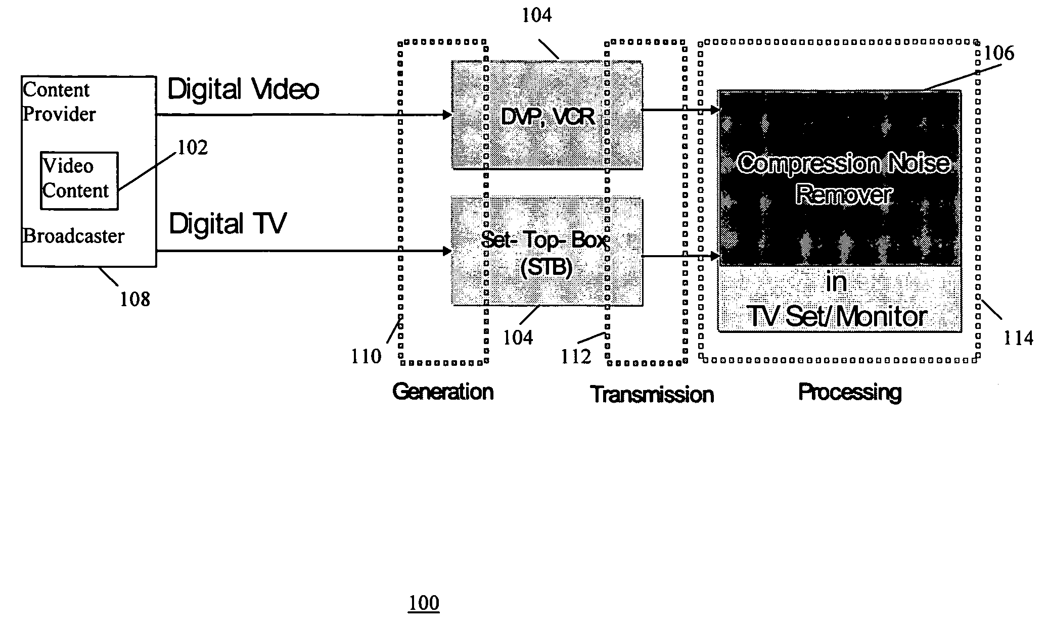
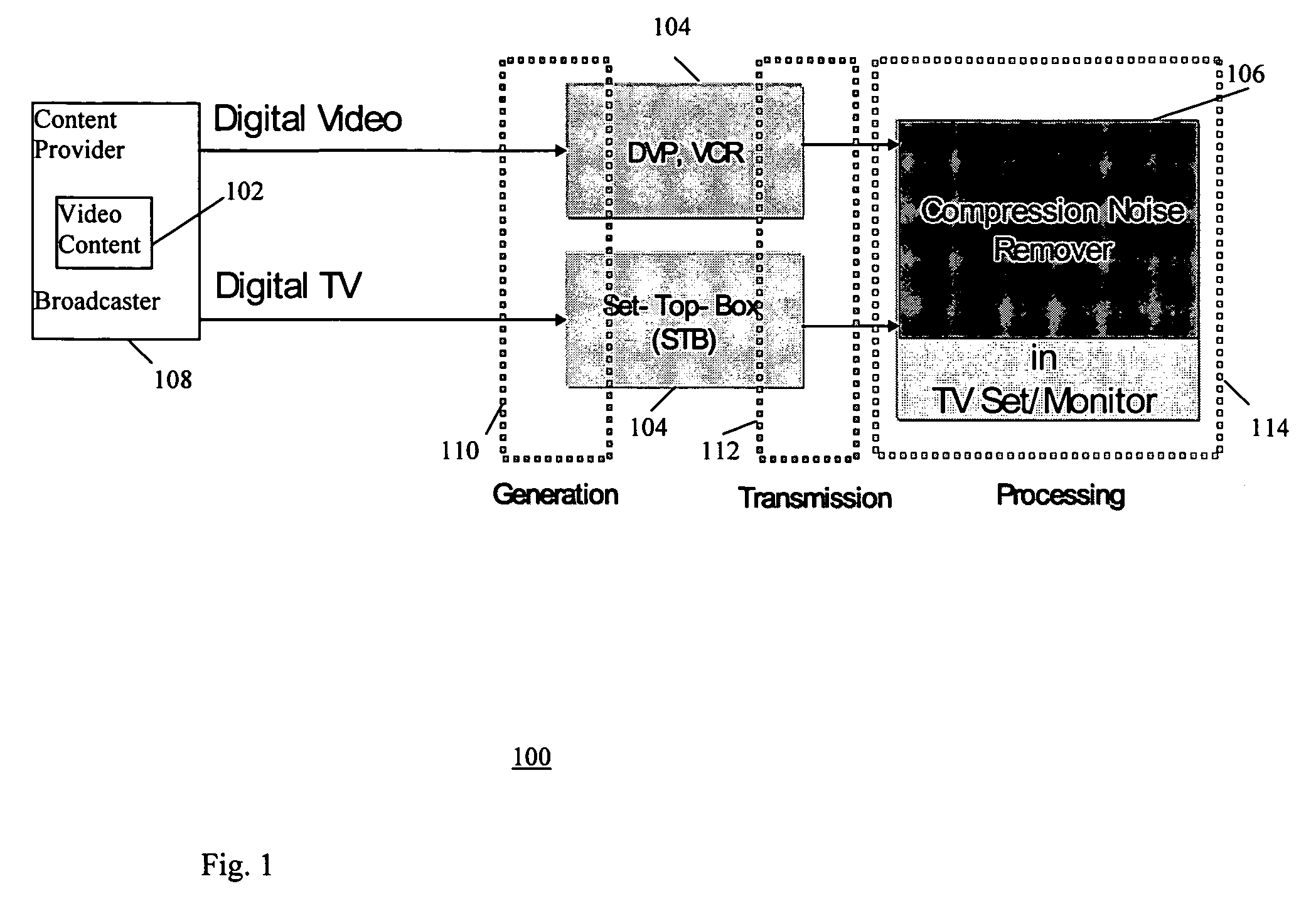
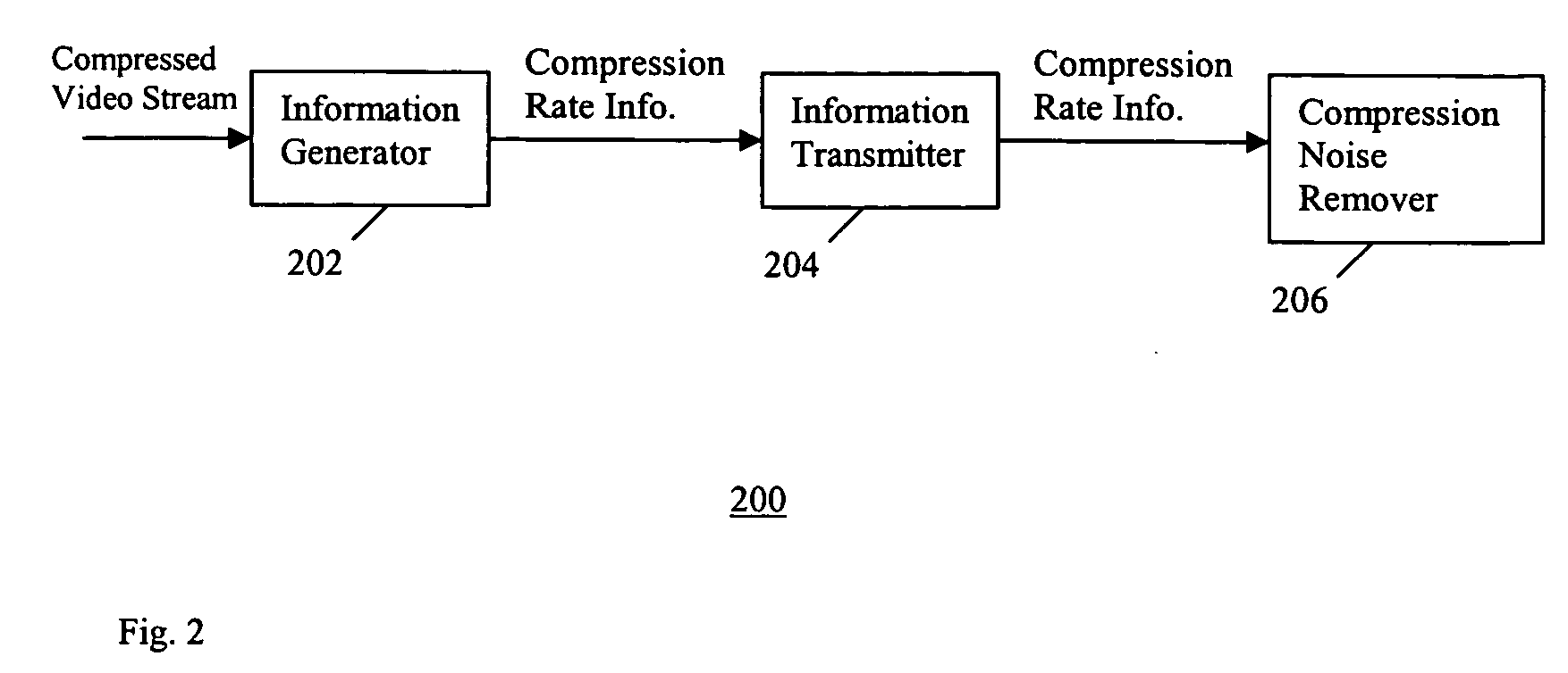
[0007] The present invention addresses the above needs. In one embodiment the present invention provides a video processing method and system that obtains, transmits, and processes digital video compression rate-information between a video receiver such as a Set-top-box (STB) and a display device such as a TV set. The compression rate information is obtained by the video receiver and delivered to a compression noise reducer in the display device. The compression rate information provides an indication of how much compression noise might be embedded into an incoming compressed video signal and thus allows the compression noise reducer to reduce compression noise from the incoming video signal more effectively and efficiently.
[0010] The video receiver can further comprise a video processor including a watermark extractor and a compression noise reducer, wherein the watermark extractor extracts the compression information from the communication protocol, and the compression noise reducer reduces compression noise in the received video information based on the extracted compression rate information.
[0011] The video receiver can further comprise a video processor including a detector and a compression noise reducer, wherein the detector extracts the compression information from the communication protocol after detecting a blanking interval, and the compression noise reducer reduces compression noise in the received video information based on the extracted compression rate information.

Problems solved by technology

These MPEG processed digital videos contain varying degrees of unwanted artifacts that deteriorate the quality of displayed video images and scenes.
However, these heavily compressed videos exhibit a higher level of compression noise.

Method used


Image

  • Method and apparatus for reduction of compression noise in compressed video images
  • Method and apparatus for reduction of compression noise in compressed video images
  • Method and apparatus for reduction of compression noise in compressed video images

Examples


Embodiment Construction

[0021] Video compression refers to decreasing the amount of data (e.g., number of bits per second), that represents a given video signal by exploiting spatiotemporal redundancy within the video signal. Examples of such compression techniques include Motion-JPEG, MPEG, H.26x, AVI, etc., wherein the degree of compression of digital video is represented by a range of measurable parameters, such as compression rate. Digital video includes a sequence of images, or video, generated by e.g. sampling and quantization applied to analog video signals.

[0022] Compression rate can be selected by, for example, the content producer and the broadcasting service provider, and retrieved by, for example, the receiver / decoder such as digital set-top-box (STB) or DVD player at the user site. The compression rate can be transmitted from the receiver / decoder at the user site (e.g., digital STB or DVP), to a signal processing module such as a compression noise remover (reducer) in a TV set or monitor. The...


PUM


Abstract

A video processing method and system that obtains, transmits, and processes digital video compression rate information between a video receiver such as a Set-top-box (STB) and a display device such as a TV set. The compression rate information is obtained by the video receiver and delivered to a compression noise reducer in the display device. The compression rate information provides an indication of how much compression noise might be embedded into an incoming compressed video signal and thus allows the compression noise reducer to reduce compression noise from the incoming video signal more effectively and efficiently.

Description

FIELD OF THE INVENTION [0001] The invention relates in general processing of digital video image information, and in particular to reduction of compression noise in compressed video image information. BACKGROUND OF THE INVENTION [0002] Increasingly, visual communication systems and applications advocate larger screens and higher resolutions. This trend is driven by the appearance of large CRT, LCD, PDP, and projector High-Definition (HD) TVs, and is further fueled by proliferation of digitally processed and stored visual information in the form of MPEG, DVD, DV, etc, in the consumer electronics market. As such, it becomes very important to improve the quality of images and videos that are displayed on large screens at high resolution. TV sets often implement video post-processing functions that improve and enhance the image / video signals to be displayed. Post-processing in TV sets perform functions including scaling, compression noise reduction, detail enhancement, and color enhance...

Claims


Application Information

Patent Timeline
Patent Type & Authority Applications(United States)
IPC IPC(8): H04N11/04H04B1/66H04N11/02H04N7/12
CPCH04N19/86H04N5/21H04N7/24H04N21/40
Inventor HA, VICTOR HYEONG-SEOKKIM, YEONG-TAEG
Owner SAMSUNG ELECTRONICS CO LTD
Learn More