Device for the abrasive machining of surfaces of elements and in particular optical elements or workpieces

a technology for abrasive machining and optical elements, applied in the direction of grinding/polishing apparatus, grinding machine, abrasive apparatus, etc., can solve the problems of large outlay, large polishing error, and always arisen problems with conventional methods and devices

Inactive Publication Date: 2006-06-29
FAHNLE OLIVER
View PDF12 Cites 11 Cited by
  • Summary
  • Abstract
  • Description
  • Claims
  • Application Information

AI Technical Summary

Problems solved by technology

Problems always arise with conventional methods and devices when a spherical surfaces are to be produced.
However, for reasons of time and cost, a spherical surfaces are frequently only ground along a track; the polishing is then effected not along a track but on a large surface.
Particularly when the asphericity is comparatively large, as is the case for example with progressive spe...

Method used


Image

  • Device for the abrasive machining of surfaces of elements and in particular optical elements or workpieces
  • Device for the abrasive machining of surfaces of elements and in particular optical elements or workpieces
  • Device for the abrasive machining of surfaces of elements and in particular optical elements or workpieces

Examples


Embodiment Construction

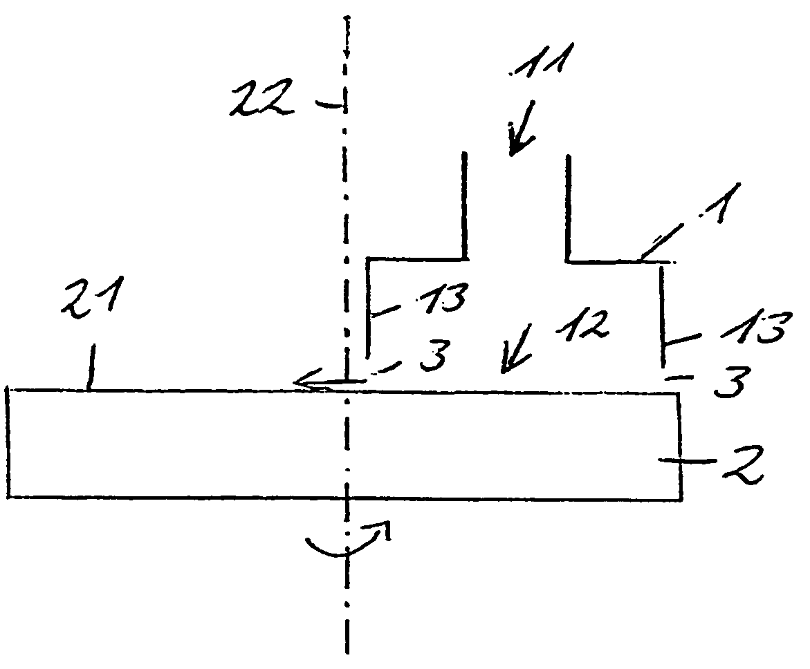
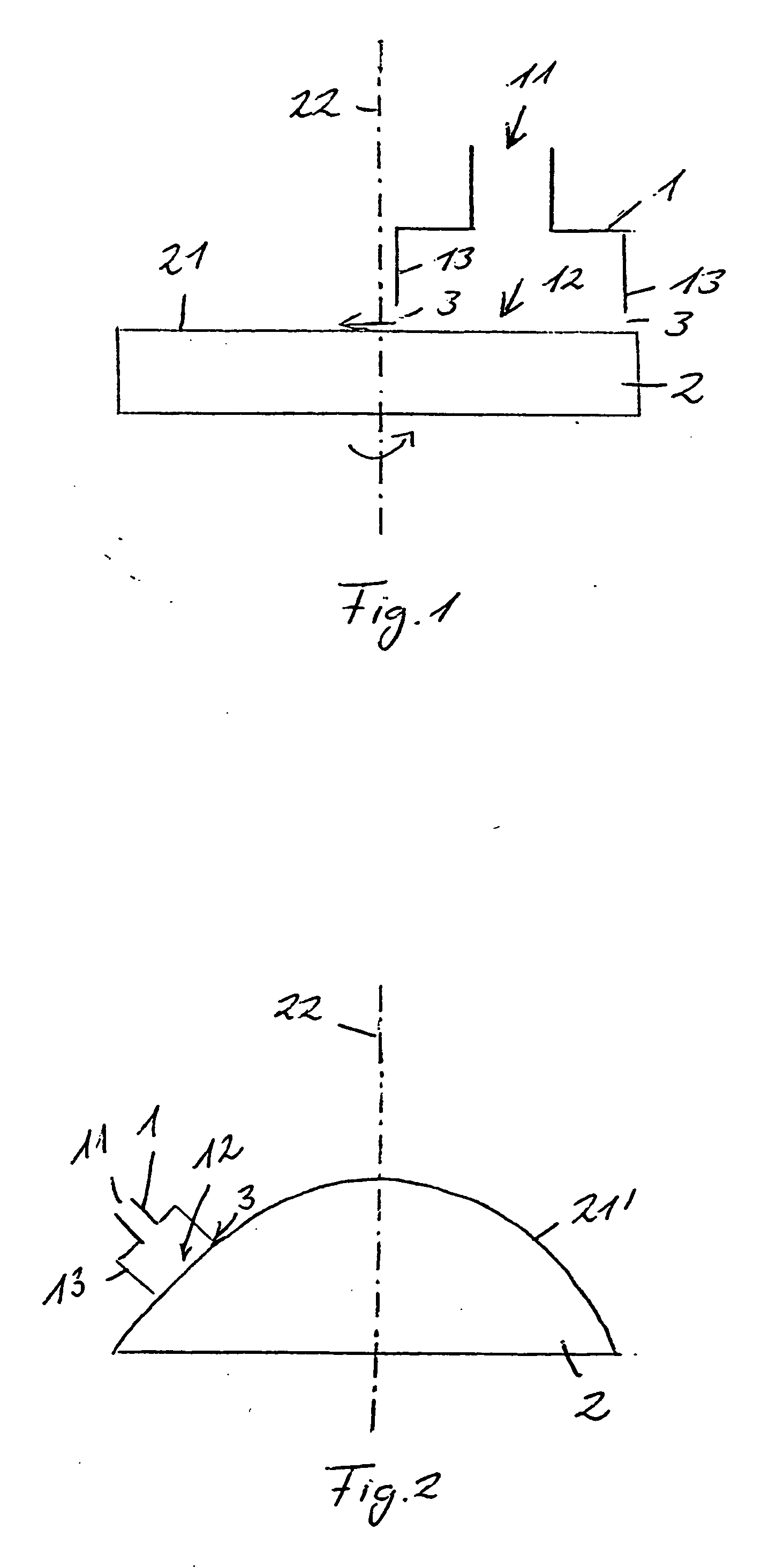
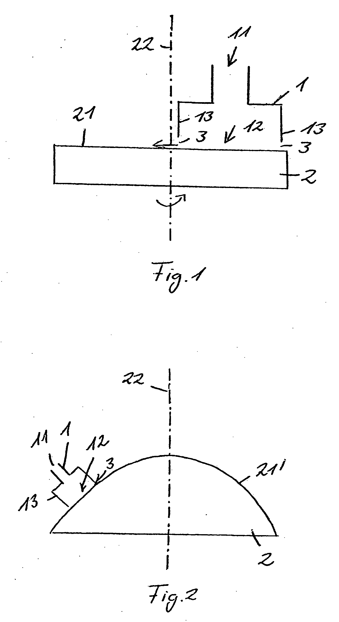
[0005] The invention is based on the object of providing a device for abrasive machining of surfaces, and particularly for grinding and / or polishing of surfaces of optical components, which permits fast machining of the surface irrespective of the shape of the particular surface being machined.

[0006] An achievement of the object in accordance with the invention is set out in patent claim 1. Further developments of the invention are the subject matter of claims 2 to 10. Possible uses of the device of the invention are claimed in claims 11 to 14.

[0007] In accordance with the invention, the device for abrasive machining of surfaces and particularly for grinding and / or polishing optical components comprises a tool having a fluid inlet and a fluid outlet. A supply unit conveys a liquid in which abrasive agents are dissolved to the fluid inlet. This liquid flows through the tool to an outlet from which it emerges from the tool. According to the invention, this tool is positioned by a po...


PUM

PropertyMeasurementUnit
Pressureaaaaaaaaaa
Pressureaaaaaaaaaa
Heightaaaaaaaaaa

Abstract

A device for abrasive machining of surfaces of components, comprising a tool (1) having an inlet (11) and an outlet (12); a supply unit for conveying to the inlet (11) a liquid in which abrasive agents are dissolved and which emerges from the outlet (12); and a positioning means which guides the tool across a surface to be machined and simultaneously positions the tool in such manner that the outlet faces the surface to be machined, an area of an annular gap (3) defined by boundary walls (13) of the outlet (12) and the surface (2) to be machined being smaller than a cross-sectional area of the inlet (11).

Description

TECHNICAL FIELD [0001] The invention relates to a device for abrasive machining of surfaces of components, particularly optical components or work pieces. PRIOR ART [0002] Various methods and devices are known for abrasively machining surfaces, as is necessary for example for the manufacture of optical components such as lenses, prisms, plane parallel plates etc, but also of molds for casting or molding optical components,. With many of the known methods or devices a surface to be machined is first subjected to a grinding operation, and possibly also to a fine grinding operation using contacting tools such as, for example, disk-wheel grinders, spherical grinders etc., and subsequently to a polishing operation using a polishing tool. Instead of applying grinding operations it is also known to subject the surfaces to turning using a suitable lathe chisel on a lathe, or to apply another machining-down method. Most machining operations in which relatively much material is removed requir...

Claims


Application Information

Patent Timeline
IPC IPC(8): B24C3/00B24B13/00B24B31/116B24C1/08
CPCB24B13/00B24B31/116B24C1/08
Inventor FAHNLE, OLIVER
Owner FAHNLE OLIVER
Why Eureka
Try Eureka